Roller bearing for wind turbines

a technology for wind turbines and bearings, applied in the direction of bearings, roller bearings, shafts, etc., can solve the problems of requiring specialized equipment, and affecting the maintenance effect of bearings supporting the main shaft of the blade rotor assembly,

Active Publication Date: 2014-04-24
SCHAEFFLER TECH AG & CO KG
View PDF12 Cites 44 Cited by
  • Summary
  • Abstract
  • Description
  • Claims
  • Application Information

AI Technical Summary

Problems solved by technology

In large size wind turbines, the nacelle can be dozens of feet above the ground, thus maintaining the bearings supporting the main shaft of the blade rotor assembly can involve substantial labor, costs and often the use of specialized equipment, such as large cranes.

Method used


Image

  • Roller bearing for wind turbines
  • Roller bearing for wind turbines

Examples


Embodiment Construction

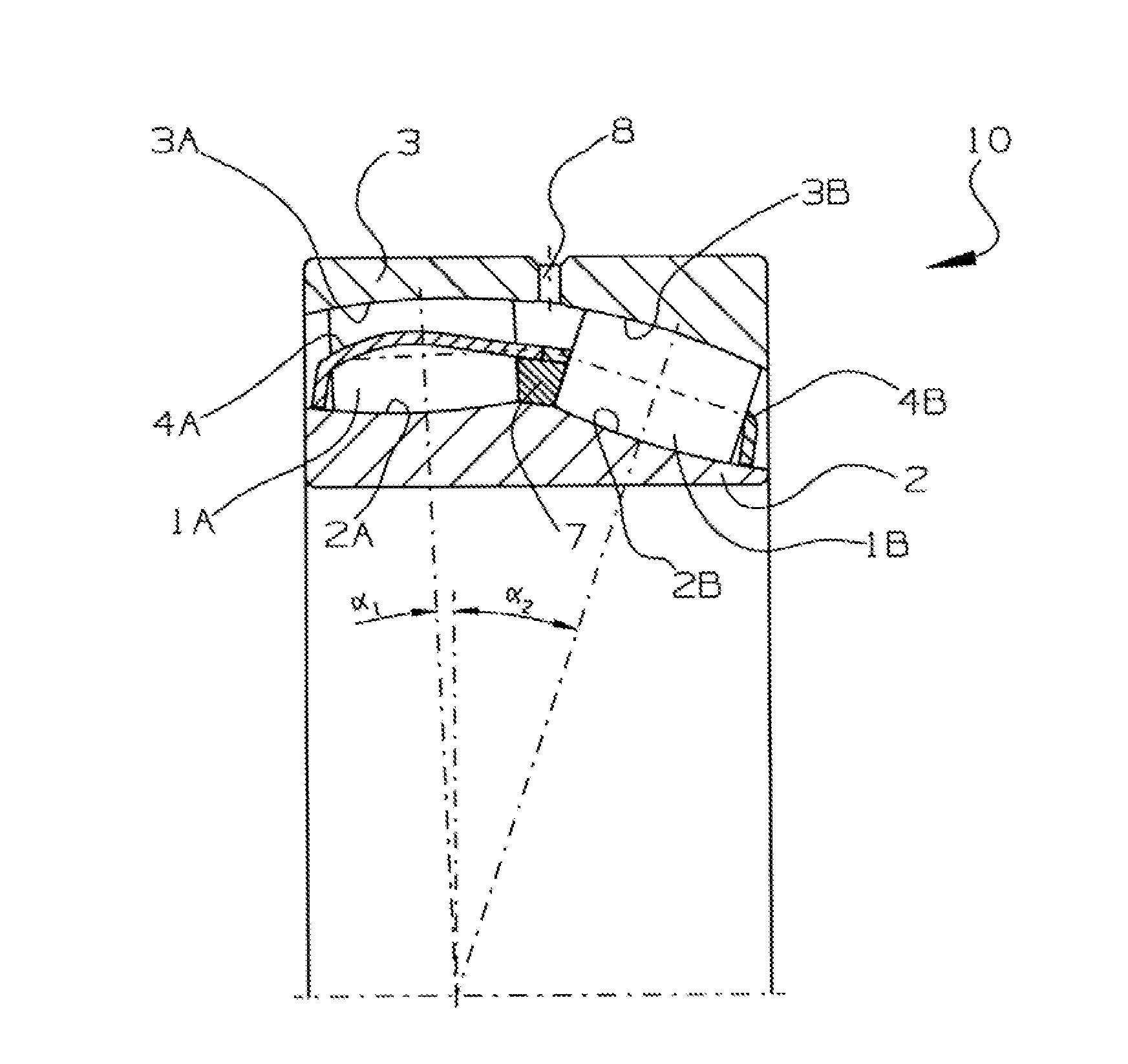
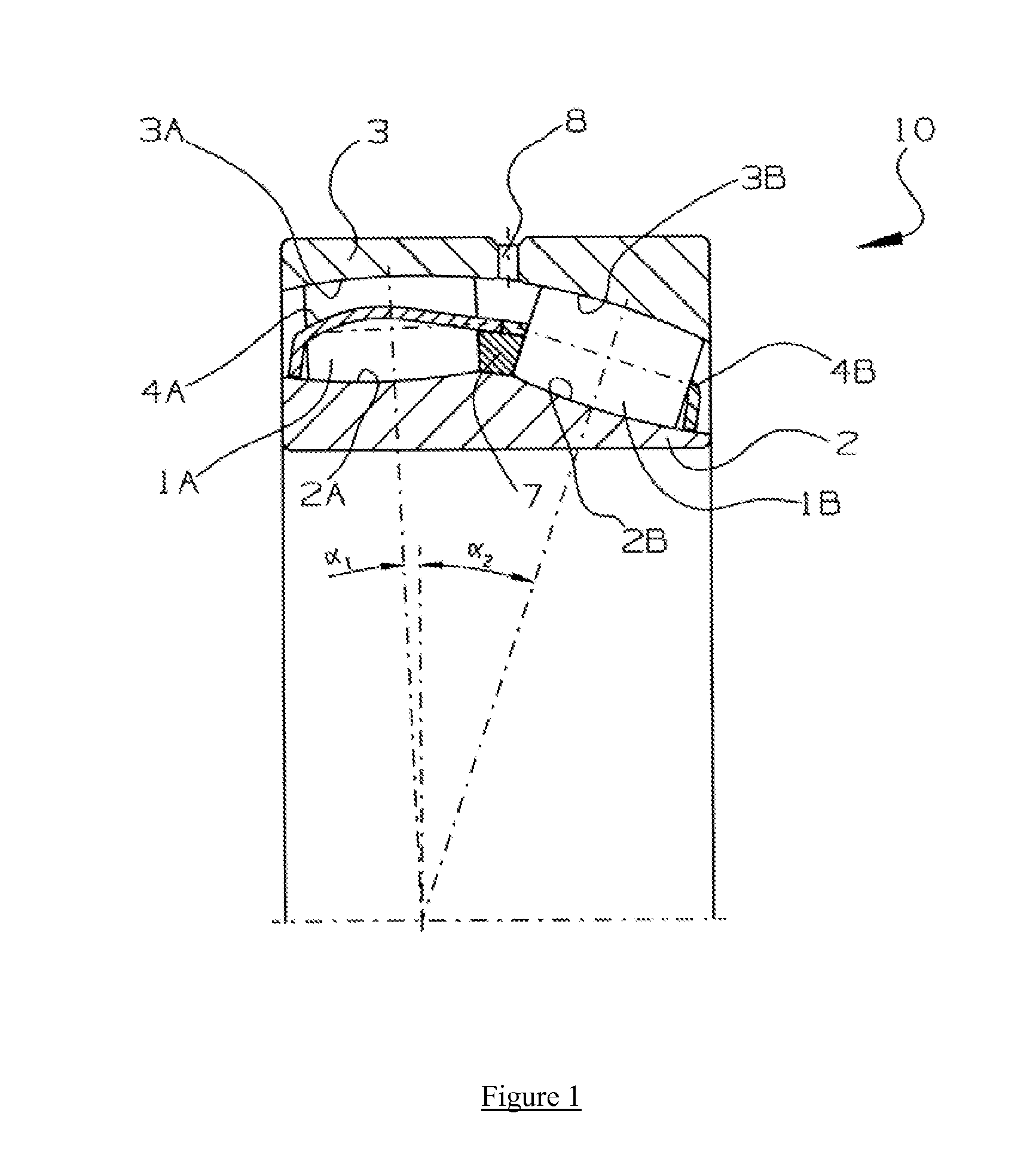
[0009]Identically labeled elements appearing in different ones of the figures refer to the same elements but may not be referenced in the description for all figures. The exemplification set out herein illustrates at least one embodiment, in at least one form, and such exemplification is not to be construed as limiting the scope of the claims in any manner. Radially inward directions are from an outer radial surface of the cage, toward the central axis or radial center of the cage. Conversely, a radial outward direction indicates the direction from the central axis or radial center of the cage toward the outer surface. Axially refers to directions along a diametric central axis.

[0010]FIG. 1 is a cross sectional view of bearing assembly 10 according to one example embodiment of the invention. Bearing assembly 10 comprises inner ring 2 having inner races 2A and 2B on a radially inner circumferential surface, outer ring 3 having outer races 3A and 3B on a radially outer circumferential...


PUM


Abstract

A self aligning bearing assembly comprising an inner ring and an outer ring, and two rows of rolling elements of equal length arranged at different contact angles, for supporting a main shaft of a wind turbine.

Description

TECHNICAL FIELD[0001]Example aspects described herein relate to bearing assemblies, particularly of self-aligning bearings for wind turbine applications.BACKGROUND[0002]Bearing assemblies are typically circular in shape, and generally comprise rolling elements disposed between raceways in bearing rings. Rolling elements take many forms, including spherical balls, rollers or various other configurations, such as cone-shaped tapered rollers or barrel-shaped spherical rollers.[0003]Bearings are widely used in wind power generation, particularly in the nacelle of the turbine, to support components in the gearbox and the main shaft of the wind turbine, which, typically the blade rotor assembly is mounted on. In large size wind turbines, the nacelle can be dozens of feet above the ground, thus maintaining the bearings supporting the main shaft of the blade rotor assembly can involve substantial labor, costs and often the use of specialized equipment, such as large cranes.[0004]Both radial...

Claims


Application Information

Patent Timeline
Patent Type & Authority Applications(United States)
IPC IPC(8): F16C23/08
CPCF16C23/082F16C23/086F16C2300/14F16C2360/31F16C2240/34F16C33/37F16C33/485F16C19/38F03D13/00F16C33/00F16C33/60F16C33/64
Inventor SILVERIO, ANTONIOGREENFIELD, RYAN
Owner SCHAEFFLER TECH AG & CO KG
Why Eureka
Try Eureka