Modular Terminal Block

a module terminal and terminal block technology, applied in the direction of electrical apparatus, connection, coupling device connection, etc., can solve the problem of high manufacturing and inventory cost of different size modules in order to accommodate different size circuit boards, and achieve the effect of reducing manufacturing and inventory cos

Active Publication Date: 2014-04-24
PHOENIX CONTACT DEVMENT & MFG
View PDF0 Cites 14 Cited by
  • Summary
  • Abstract
  • Description
  • Claims
  • Application Information

AI Technical Summary

Benefits of technology

[0007]Different size extender bodies are mounted on standard contact bodies in order to provide different size recesses for different size electronic components. The use of

Problems solved by technology

The manufacture of different size modules in order to

Method used


Image

  • Modular Terminal Block
  • Modular Terminal Block
  • Modular Terminal Block

Examples


first embodiment

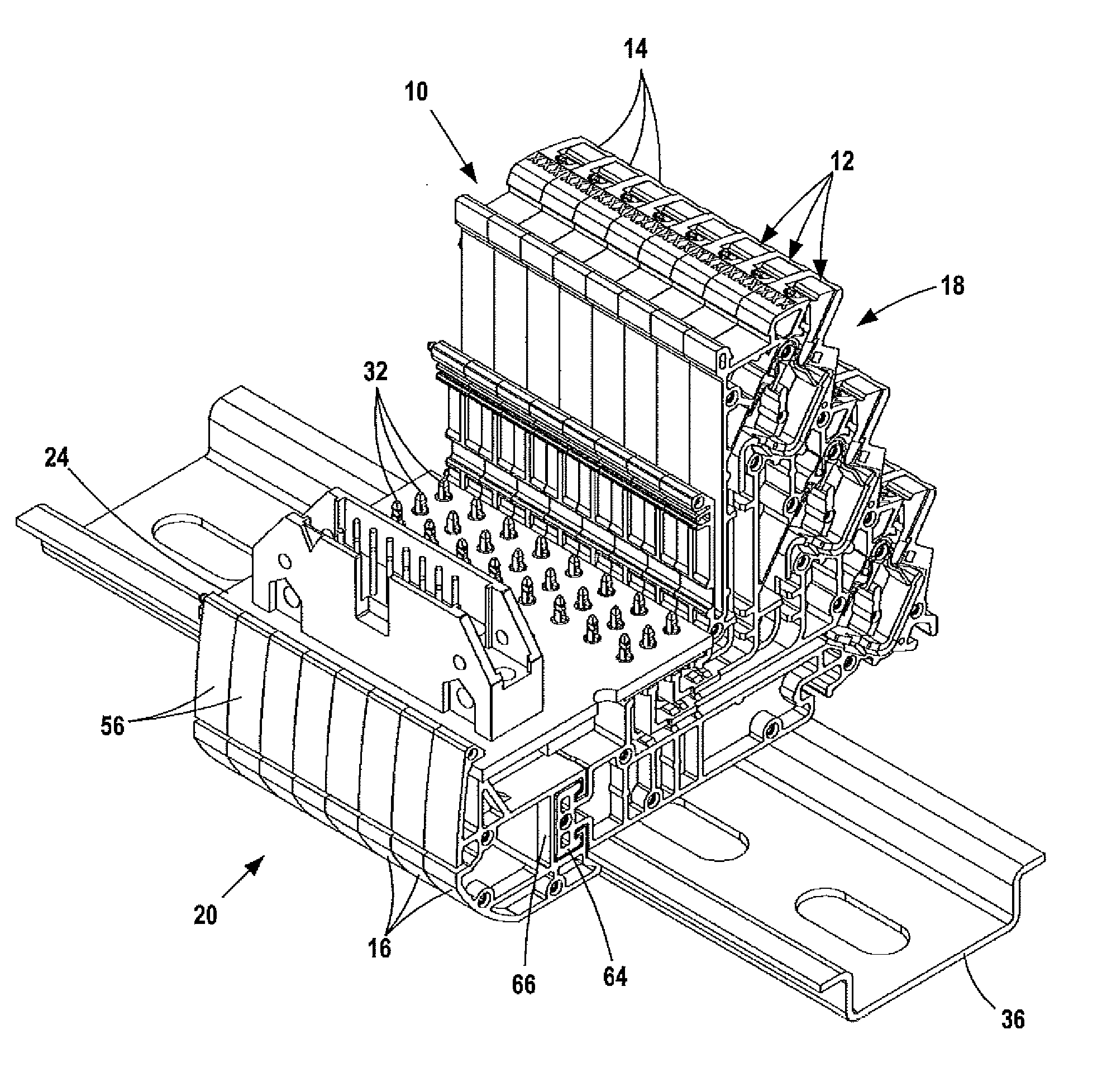
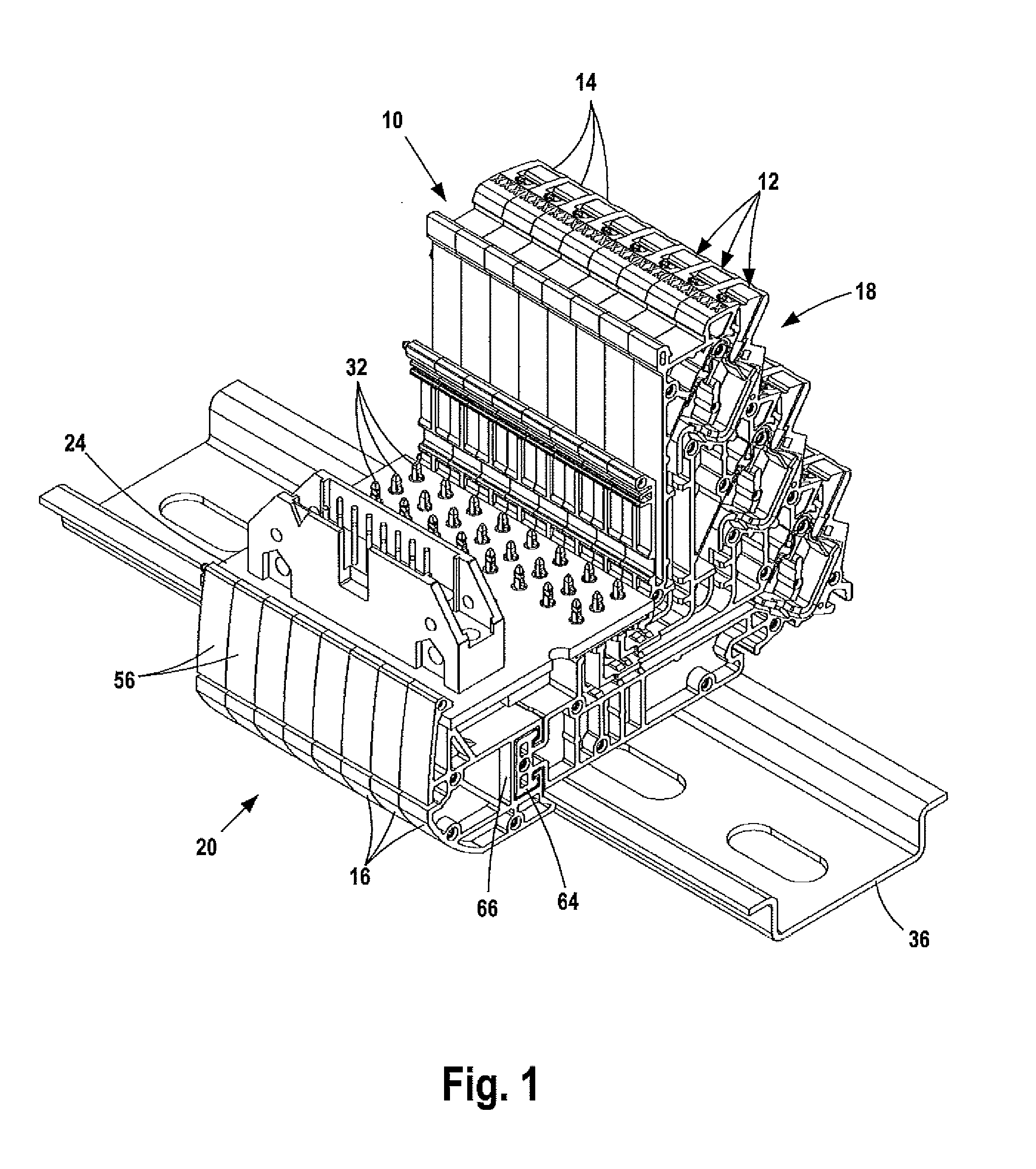
[0017 modular terminal block 10, shown in FIGS. 1-7, includes a plurality of identical flat and uniform thickness slices or modules 12. The slices are stacked and together form the block. End plates (not illustrated) are snapped on the ends of the block.

[0018]Each slice 12 includes a molded plastic contact body 14 and a molded plastic extender body 16. Contact bodies 14 are located on input / output side 18 of the block 10. Extender bodies 16 are located on circuit board side 20, across the slices from the input / output side 18. The assembled slices form a circuit board or electronic component recess or space 22 located between sides 18 and 20. The length of the extender bodies determines the width of recess 22 and the width of circuit board 24 or component mounted in recess 22. Different length extenders may be mounted on contact bodies 14 to provide a recess 22 for support of a given width board or component.

[0019]Slices 12 have opposed, parallel sides 26 and 28. Three formed metal l...

second embodiment

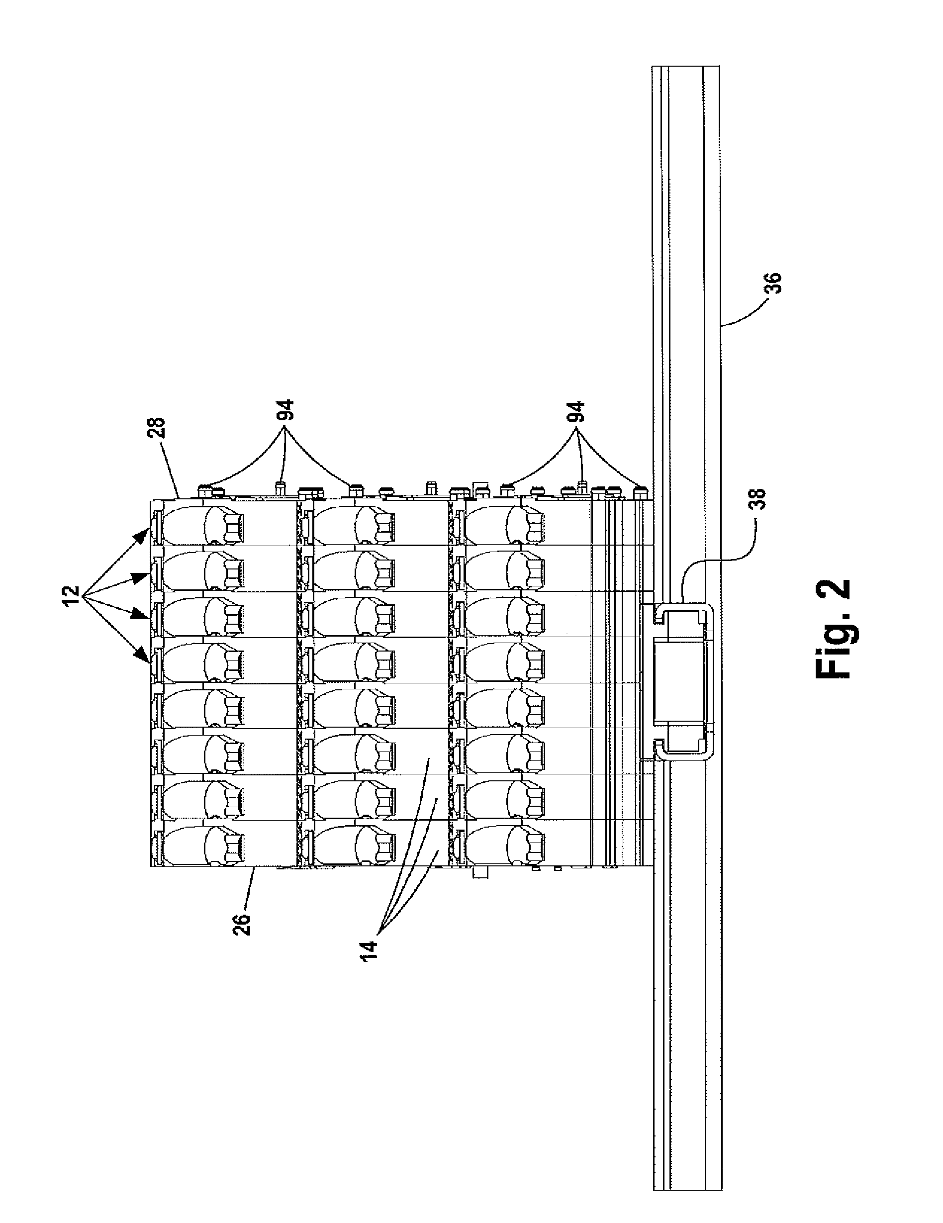
[0031]FIG. 8 illustrates a second embodiment modular terminal block 100 with a plurality of slices 102. Each slice has a contact body 104 and an extender body 106. Bodies 104 are like bodies 14. Extender bodies 106 have a greater length away from the bodies 104 than extender bodies 16 to form an enlarged recess 108 to accommodate wide circuit board 110. Each extender body 106 is mounted on a body 104 by press-fit engagement between a T-shaped mounting member 114 on body 104 and a T-shaped opening 116 on the extender body. Mounting member 114 is like mounting member 64. Opening 116 is like mounting opening 66. The extender bodies are mounted on contact bodies 104 the same way as illustrated in FIG. 5. Block 100 is mounted on DIN rail 118.

[0032]The distance between the opposed sides of block 100 is greater than the corresponding distance between the opposed sides of block 10. In order to properly balance block 100 on DIN rail 118, the center line of rail 118 should be as close as poss...


PUM


Abstract

A terminal block for mounting on a DIN rail includes a plurality of stacked modules with each module having a contact body and an extender body mounted on the contact body. A circuit board or electronic component is mounted on the contact body and the extender body. Different size extender bodies may be mounted on a common contact body to accommodate mounting different size circuit boards or components on the block.

Description

FIELD OF INVENTION[0001]The invention relates to a modular terminal block mounted on a DIN rail for connecting wires mounted on the block and an electronic component, which may be a circuit board, mounted on the block.BACKGROUND OF THE INVENTION[0002]DIN rail-mounted terminal blocks for forming electrical connections between wires and circuit boards mounted on the block are known. The blocks are typically constructed from a number of like, stacked modules which are secured together by snap-fasteners. The blocks are mounted on DIN rails.[0003]Each module in the block includes wire contacts for forming connections with a number of wires and leads extending from the wire contacts to ends for forming electrical connections with a circuit board mounted on a recess in the block. The recess is sized to fit the component. Blocks accommodate one size circuit board only. Different size modules are required to accommodate different size circuit boards.[0004]The manufacture of different size mo...

Claims


Application Information

Patent Timeline
IPC IPC(8): H01R9/22
CPCH01R13/506H01R9/26H01R9/2408
Inventor BARBER, TERRY LEECORRELL, MICHAEL ANTHONYBRAUNS, MICHAEL
Owner PHOENIX CONTACT DEVMENT & MFG
Why Eureka
Try Eureka