Multi-voltage pump with discreet voltage cords

a voltage cord and multi-voltage technology, applied in the direction of electrical equipment, substation/switching arrangement details, coupling device connections, etc., can solve the problems of reducing the service life of the system, increasing the cost, and rework costs, so as to reduce the inventory cost, the effect of easy and quick selection of cord lengths

Active Publication Date: 2011-04-26
CRANE PUMPS & SYST INC
View PDF21 Cites 22 Cited by
  • Summary
  • Abstract
  • Description
  • Claims
  • Application Information

AI Technical Summary

Benefits of technology

[0007]In contrast to known means of effecting power rating connections on, for example, motor systems by which a power connection cover is removed from the motor housing and wiring connections made accordingly, an exemplary embodiment permits the power rating connection to be made within the power cord itself. One principal advantage of this approach is that cord length selection can easily and quickly be made to meet customer requirements. By retaining a less diverse inventory, some exemplary embodiments may reduce the inventory cost throughout the distribution channel. In some exemplary embodiments, the manufacturing costs may be reduced by eliminating the need to add a cord.
[0008]Some exemplary embodiments may allow standardization of manufacturing practices that may reduce the potential for misconnections, which can result in rework costs and the potential to permanently damage system components. In certain embodiments, the cord may allow a distributor / end-user the ability to easily alter the voltage connection without having to gain access to the internals of a pump. In the case of some pumps, exemplary embodiments may eliminate the need to open the pump in the field and opening any factory sealed watertight joints.
[0010]Another object of exemplary embodiments is to reduce the number of units required to be inventoried and to realize consequent cost savings.

Problems solved by technology

This consequently and undesirably increases cost and complicates distribution requirements.
Some exemplary embodiments may allow standardization of manufacturing practices that may reduce the potential for misconnections, which can result in rework costs and the potential to permanently damage system components.

Method used


Image

  • Multi-voltage pump with discreet voltage cords
  • Multi-voltage pump with discreet voltage cords
  • Multi-voltage pump with discreet voltage cords

Examples


Embodiment Construction

[0024]Some sample embodiments of the present invention will now be described in greater detail. Nevertheless, it should be recognized that the present invention may be practiced in a wide range of other embodiments besides those explicitly described, and the scope of the present invention is expressly not limited except as specified in any accompanying claims.

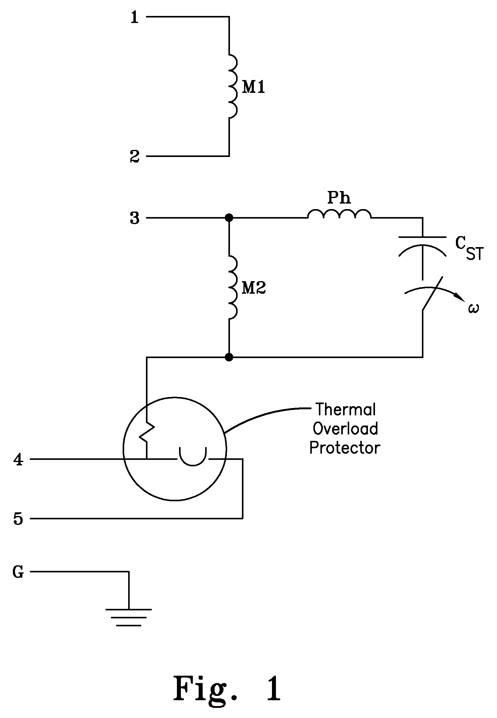
[0025]FIG. 1 illustrates how a motor typically used on, for example, a pump may be internally electrically wired and is typical for a dual-voltage capacitor start motor. Lead wires 1 and 2 are connected to opposite ends of the first part of the main winding M1. Lead wire 3 is connected to the other portion of the main winding M2 as well as the phase Ph or auxiliary winding and the start capacitor Cst and motor start switch ω. Lead wires 4 and 5 are connected to the thermal protector in the motor which is appropriately connected for a dual-voltage motor. It should be noted that exemplary embodiments may work equally well for oth...


PUM


Abstract

A device for interfacing power from an electrical supply having power terminals, that permits implementation of a wide range of power cord lengths and voltage connection combinations. The device includes a body having a cord side and an appliance side. The body has four or more terminals located on the cord side of the body, with one terminal being a ground terminal. At least one electrical connecting device is adapted to connect terminals. In a first configuration, the device is used at a lower voltage. In a second configuration, the device is used at a higher voltage.

Description

CROSS-REFERENCE TO RELATED APPLICATIONS[0001]This application claims priority of U.S. Provisional Patent Application No. 61 / 106,350, filed Oct. 17, 2008, which is incorporated by reference as if fully recited herein.TECHNICAL FIELD[0002]The present invention is directed to a device for interfacing power. More particularly, the present invention is directed to a device for interfacing power from an electrical supply having lead wires to an electrical appliance, and permits implementation of a wide range of power cord lengths and voltage connection combinations.BACKGROUND OF THE ART[0003]Many motor-operated appliances, in particular centrifugal pumps, have the capability to operate when supplied by any of several different power supplies when the appropriate electrical connection modifications are made. It is well known in the industry how to produce motors that drive pumps that are of dual-voltage design. Conversion from one voltage to the other only requires reconnection of the moto...

Claims


Application Information

Patent Timeline
Patent Type & Authority Patents(United States)
IPC IPC(8): H01R29/00
CPCH01R29/00Y10S439/956
Inventor WATKINS, WILLIAM J.KOWALAK, MARK
Owner CRANE PUMPS & SYST INC
Why Eureka
Try Eureka