Street ironwork

Active Publication Date: 2014-05-08
SAINT GOBAIN PAM SA
View PDF11 Cites 2 Cited by
  • Summary
  • Abstract
  • Description
  • Claims
  • Application Information

AI Technical Summary

Benefits of technology

[0011]the locking device is suitable for preventing the covering element knuckle from being released from the frame knuckle in a range of positions of the covering element relative to the frame corresponding to an angular range of assembly positions of the covering ele

Problems solved by technology

However, these hinges allow the frame and the covering element to be disass

Method used


Image

  • Street ironwork
  • Street ironwork
  • Street ironwork

Examples


Embodiment Construction

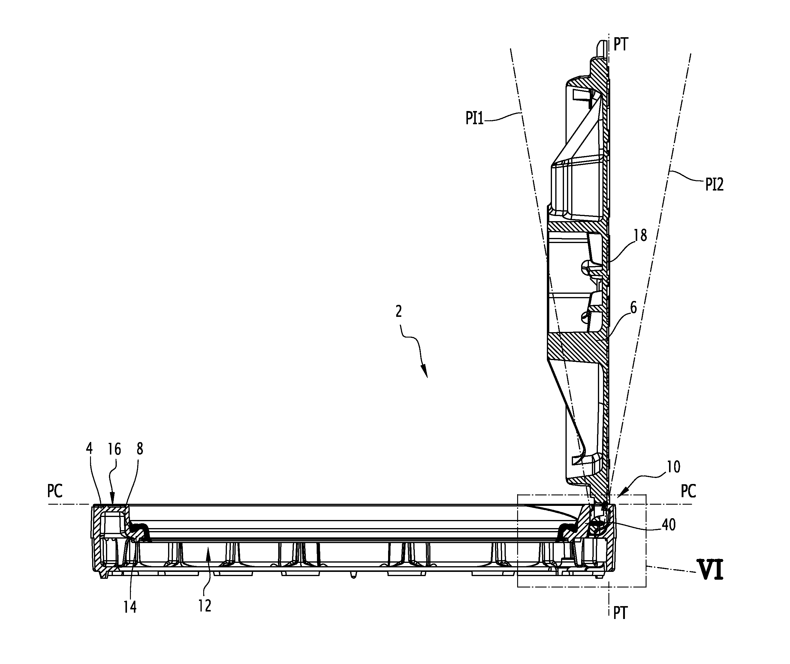
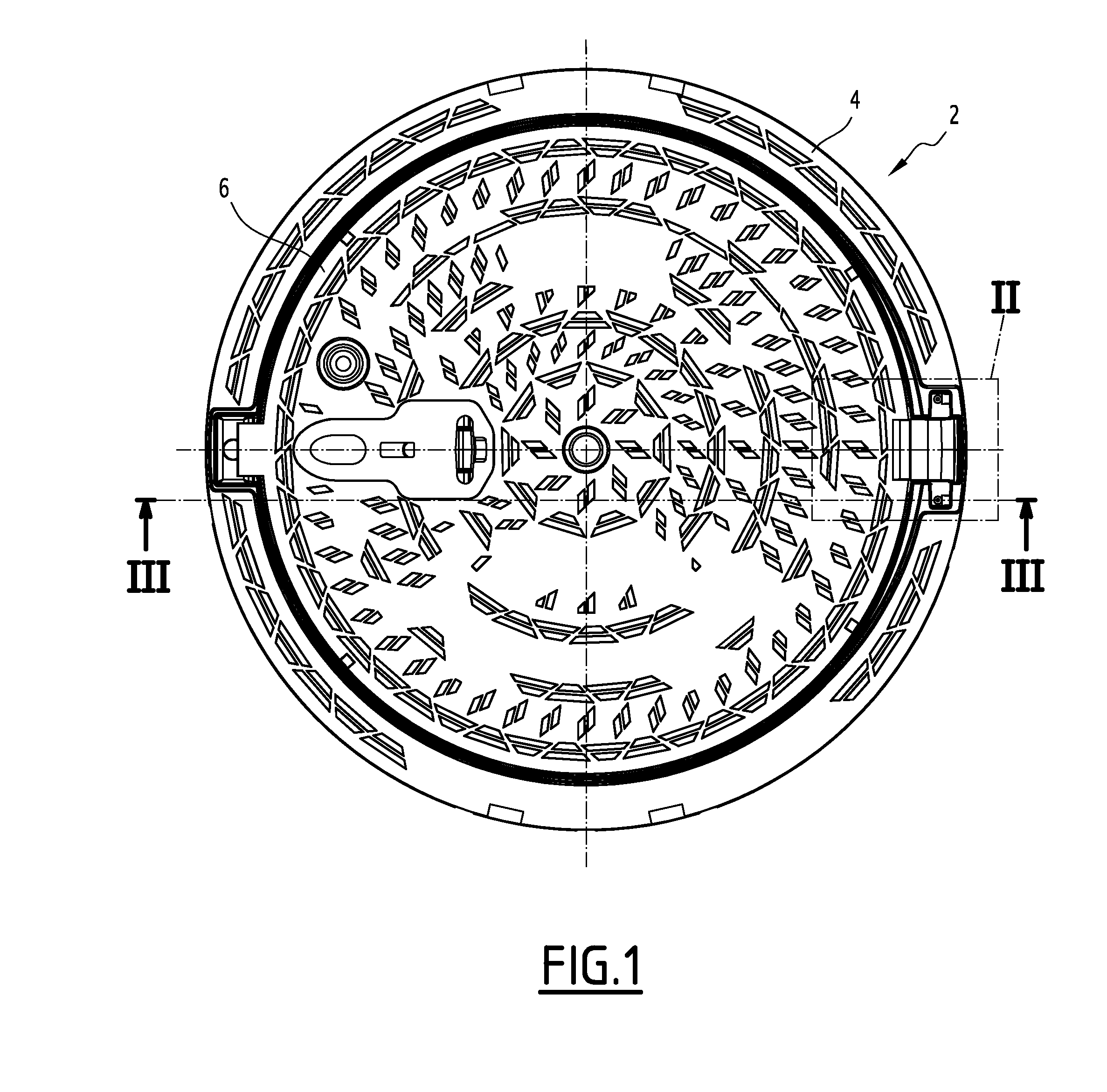
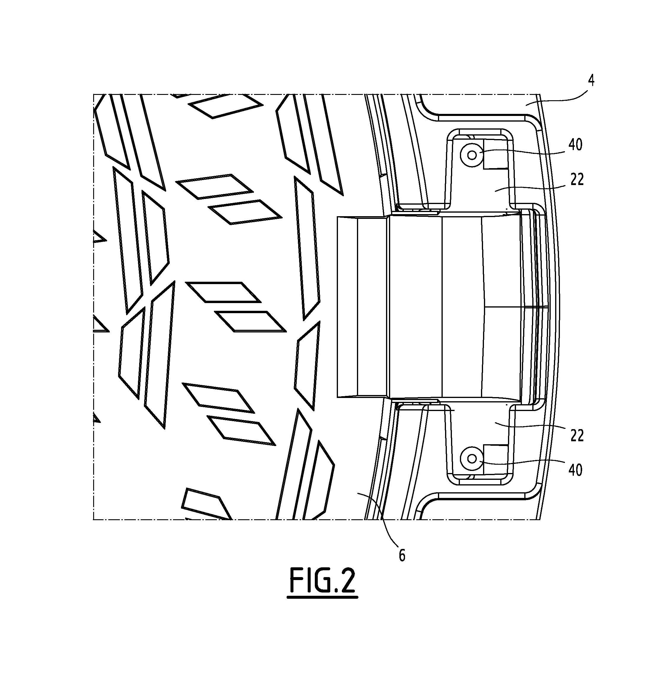
[0031]The figures show a street ironwork according to the invention, designated by general reference 2.

[0032]The street ironwork 2 comprises a frame 4, a covering element formed by a manhole cover 6, and a soundproofing seal 8. The street ironwork 2 comprises a hinge 10 pivotably connecting the manhole cover 6 relative to the frame 4.

[0033]The frame 4 defines a central access opening 12 and comprises an inner rim 14 on which the soundproofing seal 8 is positioned. The frame 4 defines an upper surface 16 surrounding the central access opening 12 extending in a frame plane PC. In the installed state, the frame plane PC is substantially parallel to the ground and is preferably aligned with the surface of the ground. The frame 4 is for example made from cast iron.

[0034]The manhole cover 6 comprises a closing web 18 pressing in the closed state on the soundproofing seal 8. The closing web 18 defines a manhole cover plane PT that extends in the closed state parallel to the frame plane PC....


PUM


Abstract

The street ironwork according to the invention includes a frame (4), a manhole cover (6), a hinge (10) for pivotably connecting the covering element relative to the frame between a closed position and an open position, the hinge including a frame knuckle (20) and a covering element knuckle (22).
The street ironwork includes a locking element (40) attached to the covering element knuckle and suitable for preventing the covering element knuckle from being released from the frame knuckle in at least one of the open positions of the covering element relative to the frame or in the closed position.

Description

FIELD OF THE INVENTION[0001]The present invention relates to a street ironwork, including:[0002]a frame,[0003]a covering element,[0004]a hinge for pivotably connecting the covering element relative to the frame between a closed position and an open position,[0005]the hinge including a frame knuckle and a covering element knuckle.DESCRIPTION OF RELATED ART INCLUDING INFORMATION DISCLOSED UNDER 37 CFR 1.97 AND 1.98 [0006]Such street ironwork devices are known. The frame knuckle and the covering element knuckle have a shape such that the covering element knuckle and the frame knuckle can be assembled through a radial relative movement with respect to an axis specific to each of the knuckles.[0007]However, these hinges allow the frame and the covering element to be disassembled by unauthorized persons, or allow the covering element to be stolen.[0008]The present invention aims to propose a street ironwork that has increased security, with simple and cost-effective means.BRIEF SUMMARY O...

Claims


Application Information

Patent Timeline
IPC IPC(8): E02D29/14
CPCE02D29/1463E02D29/1427E02D29/14E02D29/1481
Inventor BOCA, JACKYMORCEL, YVAN
Owner SAINT GOBAIN PAM SA
Why Eureka
Try Eureka