Automated Hypoxia Recovery System

Inactive Publication Date: 2014-05-08
CLARKSON UNIVERSITY
View PDF5 Cites 33 Cited by
  • Summary
  • Abstract
  • Description
  • Claims
  • Application Information

AI Technical Summary

Problems solved by technology

People are sometimes exposed to conditions where reduced availability of oxygen can cause hypoxia, where the body is deprived of sufficient oxygen resulting in decreased physical and mental capacity.
Supplemental oxygen systems can prevent and/or correct hypoxia; however these systems can fail o

Method used


Image

  • Automated Hypoxia Recovery System
  • Automated Hypoxia Recovery System
  • Automated Hypoxia Recovery System

Examples


Embodiment Construction

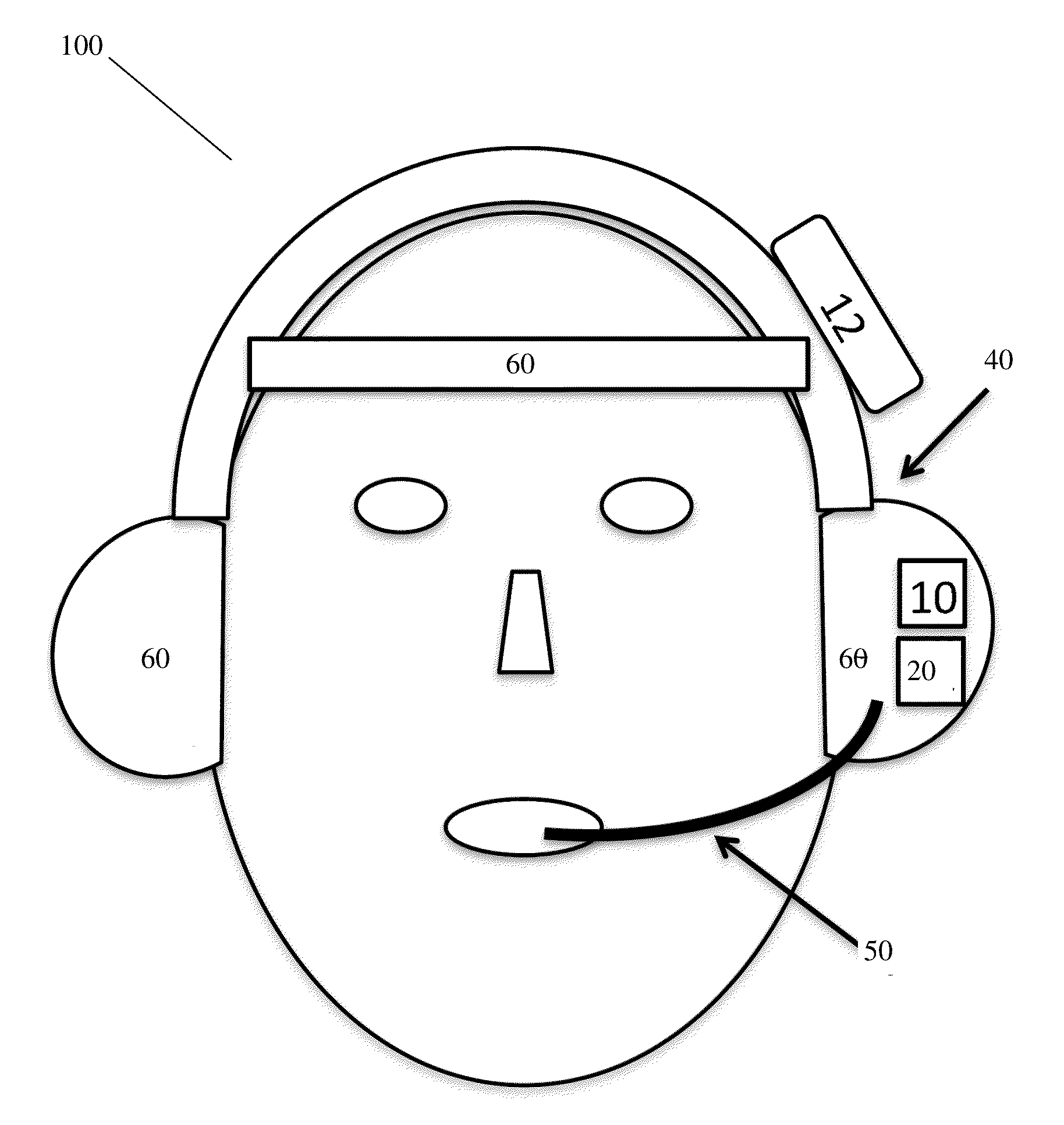
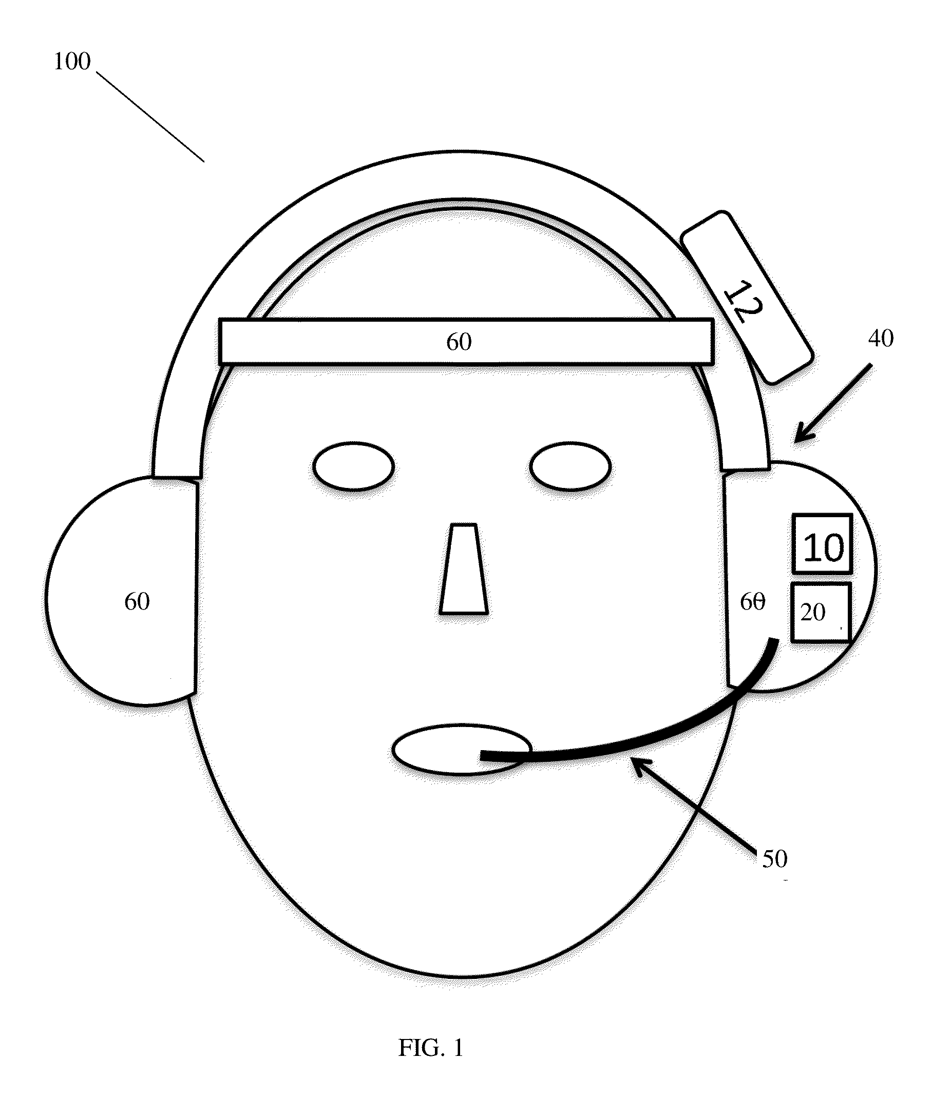
[0031]Referring now to the drawings, wherein like reference numerals refer to like parts throughout, there is seen in FIG. 1 an embodiment of an automated hypoxia recovery system 100. According to this embodiment, the wearable headset device 40 includes at least one reflectance or transmittance SpO2 sensor 60. Sensor 60 could be located at one or more of several places. For example, sensor 60 could be located at or near the forehead for measuring SpO2 levels using reflectance, or near one or both ears to measure SpO2 levels by transmittance or reflectance. Alternatively, the sensor 60 can be remote from the wearable headset device 40 and transmits SpO2 level measurements or data to the device via wired or wireless communication.

[0032]Wearable headset device 40 also includes a controller 20. The controller 20 is operably connected between the SpO2 sensor 60 and the oxygen delivery components. The controller is programmed and / or configured to receive or request SpO2 sensor data from S...


PUM


Abstract

Disclosed are methods and systems for detecting and remedying a potential hypoxic state. A wearable hypoxic state detector includes an SpO2 sensor configured to measure a user's oxygen saturation, an oxygen reservoir, an oxygen conduit positioned to deliver oxygen from the oxygen storage reservoir to the user's inhalation flow path, and a controller. The controller is operably connected between the SpO2 sensor and the oxygen delivery component, and is configured to automatically induce a flow of oxygen from the oxygen reservoir through the oxygen conduit when a predetermined oxygen saturation level is detected by the SpO2 sensor.

Description

CROSS-REFERENCE TO RELATED APPLICATIONS[0001]This application claims priority to U.S. Provisional Patent Application Ser. No. 61 / 723,033, filed on Nov. 6, 2012 and entitled “Automated Hypoxia Recovery System,” the entire disclosure of which is incorporated herein by reference.BACKGROUND[0002]The present invention relates to systems and methods for life support, and, more specifically, to systems and methods for hypoxia recovery.[0003]People are sometimes exposed to conditions where reduced availability of oxygen can cause hypoxia, where the body is deprived of sufficient oxygen resulting in decreased physical and mental capacity. Supplemental oxygen systems can prevent and / or correct hypoxia; however these systems can fail or may require human control of the system which can lead to problems due to human error. In addition, human control can become impossible after the onset of hypoxia either due to lack of recognition of the hypoxic state or the physical inability to control an oxy...

Claims


Application Information

Patent Timeline
IPC IPC(8): A61M16/00A61M16/20A61M16/06A61B5/1455A61B5/00
CPCA61M16/0051A61B5/14552A61B5/4836A61B5/7282A61M16/20A61B5/747A61M16/0057A61M16/0683A61B5/7405A61B5/14551A61B5/6803A61B2503/22A61M16/06A61M2202/0208A61M2205/18A61M2205/3331A61M2205/3358A61M2205/3569A61M2205/3592A61M2205/581A61M2205/582A61M2205/583A61M2209/088A61M2210/06A61M2230/205A61M16/0672A61M16/0677A61M16/202
Inventor RISSACHER, DANIEL JEANCARROLL, JAMES J.
Owner CLARKSON UNIVERSITY
Why Eureka
Try Eureka