
Electronic vapor inhaling device

a technology of electronic vapor and inhaler, which is applied in the direction of inhalators, medical devices, other medical devices, etc., can solve the problems of increased health risks, increased risks of smoking devices, and increased risk of health problems in many environments

Inactive Publication Date: 2012-07-12
PIRSHAFIEY NASSER +2
View PDF6 Cites 193 Cited by
  • Summary
  • Abstract
  • Description
  • Claims
  • Application Information

AI Technical Summary

Benefits of technology

[0013]In another aspect, the electronic circuit board is configured to receive input from a unique identifier associated with the electrical resistance of the liquid in the liquid storage chamber and automatically adjust the power supplied to the atomizer. The atomizer rapidly heats the liquid that is injected into an air passageway when the user inhales through the mouthpiece, causing the liquid to vaporize and allow inhalation by the user.

Problems solved by technology

Conventional smoking devices, including cigarettes, cigars and pipes, etc., are now known to be associated with a variety of problems.
Most notably, such devices typically burn tobacco that includes a variety of substances including tar, for example, that are believed to be associated with an increased risk of health problems, including life-threatening diseases such as cancer.
In addition, the burning of the tobacco naturally requires the use of a flame which consequently presents a significant fire risk in many environments.
Also, the experience of others' smoke can also be unpleasant for third-parties, especially in public venues.
However, current devices typically have numerous shortcomings including diminished battery life and power management issues, reliability issues, and the inability to efficiently adjust the voltage supplied to the atomizer to properly vaporize the liquid substrate.

Method used


Image

  • Electronic vapor inhaling device
  • Electronic vapor inhaling device
  • Electronic vapor inhaling device

Examples


Embodiment Construction

.”

BRIEF DESCRIPTION OF THE DRAWINGS

[0016]Features, aspects, and embodiments of the inventions are described in conjunction with the attached drawings, in which:

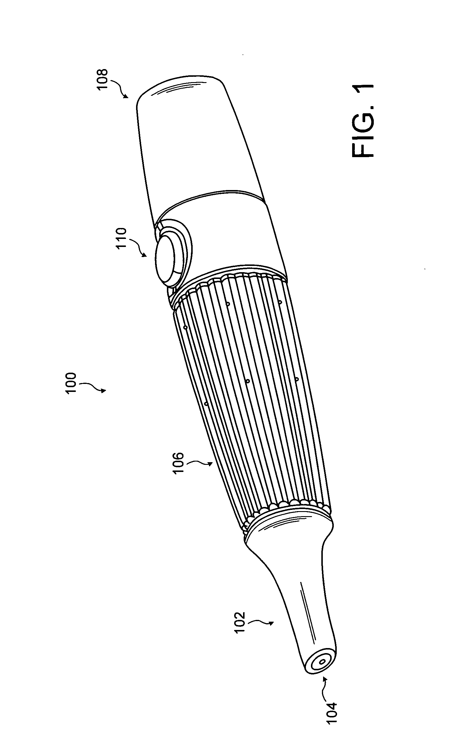
[0017]FIG. 1 illustrates a perspective view of a vapor inhaling device in one example embodiment of the invention.

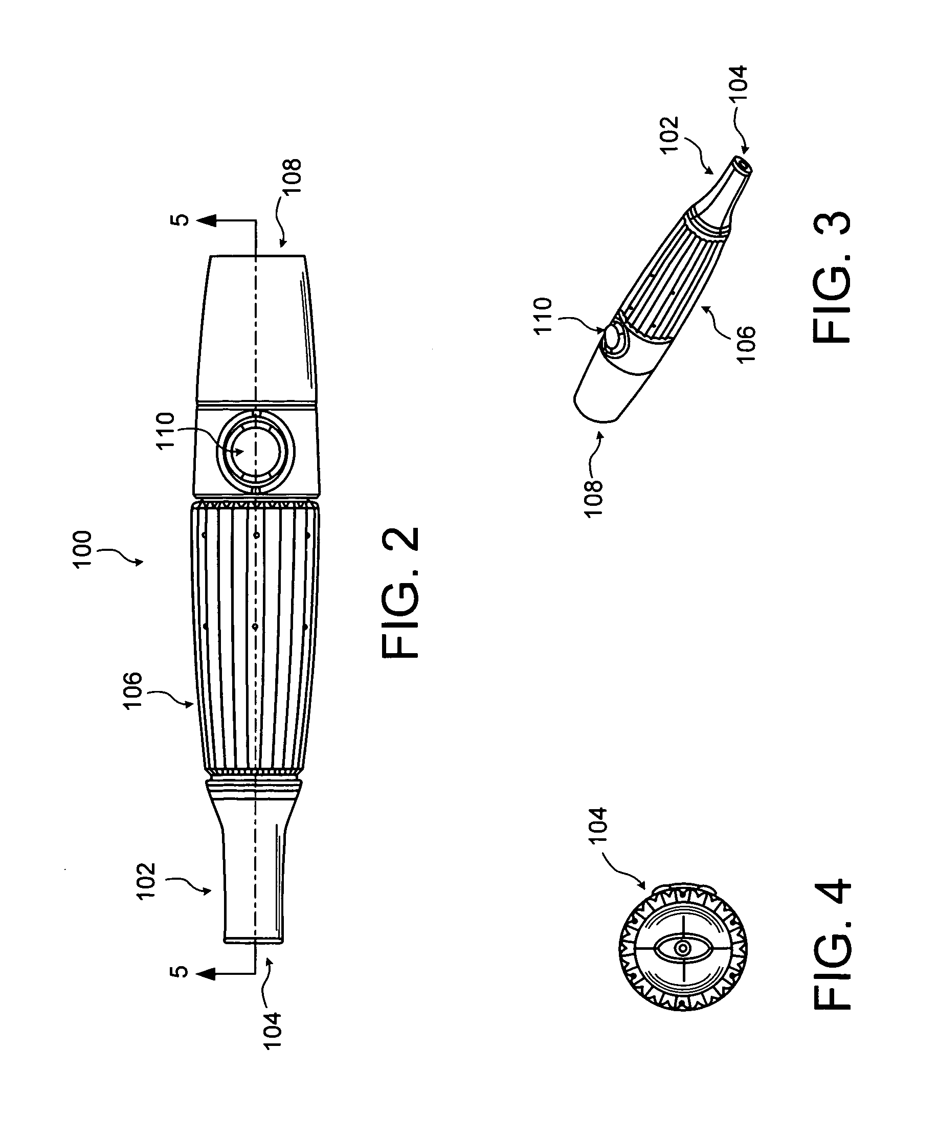
[0018]FIG. 2 illustrates a perspective view of a vapor inhaling device in another example embodiment of the invention.

[0019]FIG. 3 illustrates a perspective view of a vapor inhaling device in another example embodiment of the invention.

[0020]FIG. 4 illustrates a cross sectional view of the mouth piece of a vapor inhaling device in another example embodiment of the invention.

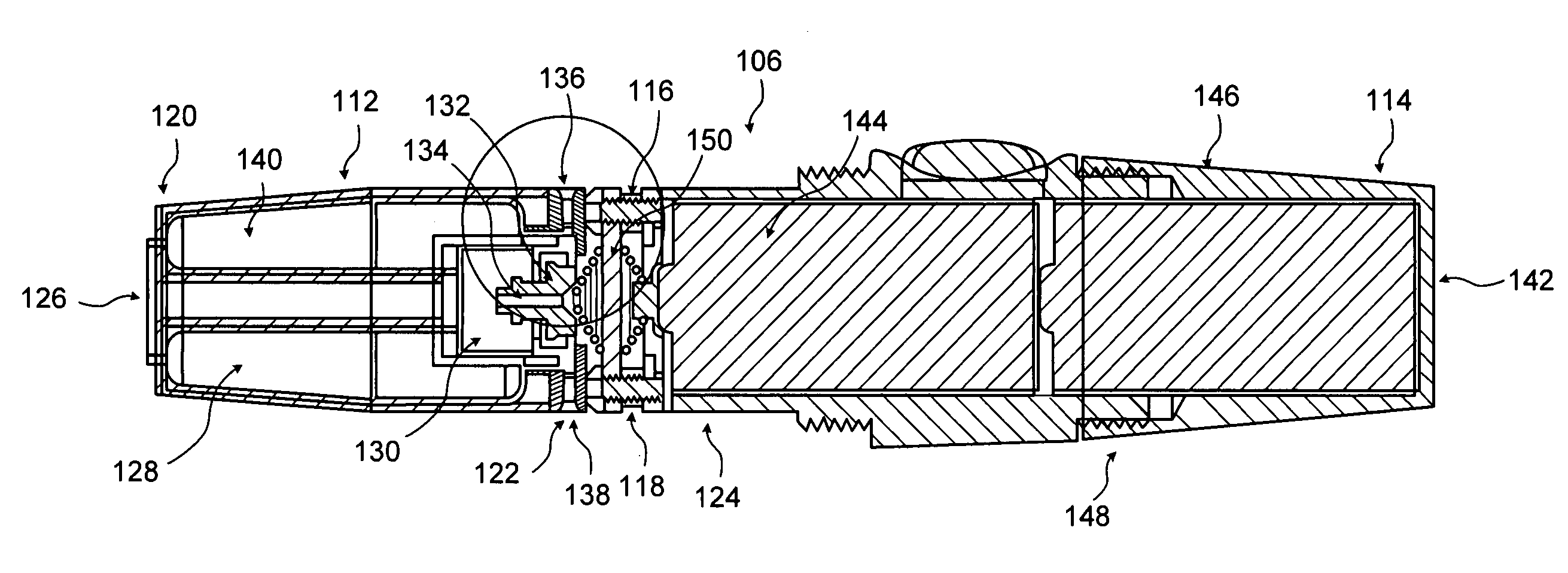
[0021]FIG. 5 illustrates a cross sectional view of the outer housing of a vapor inhaling device in another example embodiment of the invention.

[0022]FIG. 6 is an exploded view of a portion of the junction between the liquid storage chamber and battery compartment of a vapor inhaling device in another example embodiment of the invention.

[0023]FI...


PUM


Abstract

An electronic vapor inhaling device has an outer housing that defines an internal cavity having a proximal end and a distal end. A mouthpiece is located at the proximal end. A liquid storage chamber is defined within the outer housing near its proximal end and a battery compartment containing a battery is located near the distal end. An atomizer is positioned between the liquid storage chamber and battery chamber and is in communication with an electronic circuit board. The electronic circuit board is configured to receive input from a unique identifier associated with the electrical resistance of the liquid in the liquid storage chamber and automatically adjust the power supplied to the atomizer. The atomizer rapidly heats the liquid that is injected into an air passageway when the user inhales through the mouthpiece, causing the liquid to vaporize and allow inhalation by the user.

Description

CROSS-REFERENCE TO RELATED APPLICATION[0001]This application claims priority from provisional patent application Ser. No. 61 / 460,782, filed Jan. 8, 2011.STATEMENT REGARDING FEDERALLY SPONSORED RESEARCH OR DEVELOPMENT[0002]Not Applicable.REFERENCE TO A “MICROFICHE APPENDIX”[0003]Not Applicable.BACKGROUND[0004]1. Field of the Inventions[0005]The field of the invention relates to an electronic vapor inhaling device.[0006]2. Background Information[0007]Conventional smoking devices, including cigarettes, cigars and pipes, etc., are now known to be associated with a variety of problems. Most notably, such devices typically burn tobacco that includes a variety of substances including tar, for example, that are believed to be associated with an increased risk of health problems, including life-threatening diseases such as cancer. In addition, the burning of the tobacco naturally requires the use of a flame which consequently presents a significant fire risk in many environments. Also, the e...

Claims


Application Information

Patent Timeline
IPC IPC(8): A61M11/00
CPCA61M11/041A61M15/06A61M2016/0021A61M2205/3368A61M11/042A61M2205/6054A61M2205/6072A61M2205/8212A61M2205/6018
Inventor PIRSHAFIEY, NASSERMONTEZINOS, EDWARDSWERDLOFF, ERIC
Owner PIRSHAFIEY NASSER
Learn More