Method and Apparatus for Altering Biomechanics of the Articular Joints
What is AI technical title?
AI technical title is built by Patsnap AI team. It summarizes the technical point description of the patent document.
a biomechanics and articular joint technology, applied in the field of orthopaedics, can solve the problems of complex joint motion, joint pain and loss of function, bone-on-bone contact, etc., and achieve the effect of redistributing load in the join
Active Publication Date: 2014-06-05
THE FOUNDY LLC
View PDF13 Cites 24 Cited by
Summary
Abstract
Description
Claims
Application Information
AI Technical Summary
This helps you quickly interpret patents by identifying the three key elements:
Problems solved by technology
Method used
Benefits of technology
Benefits of technology
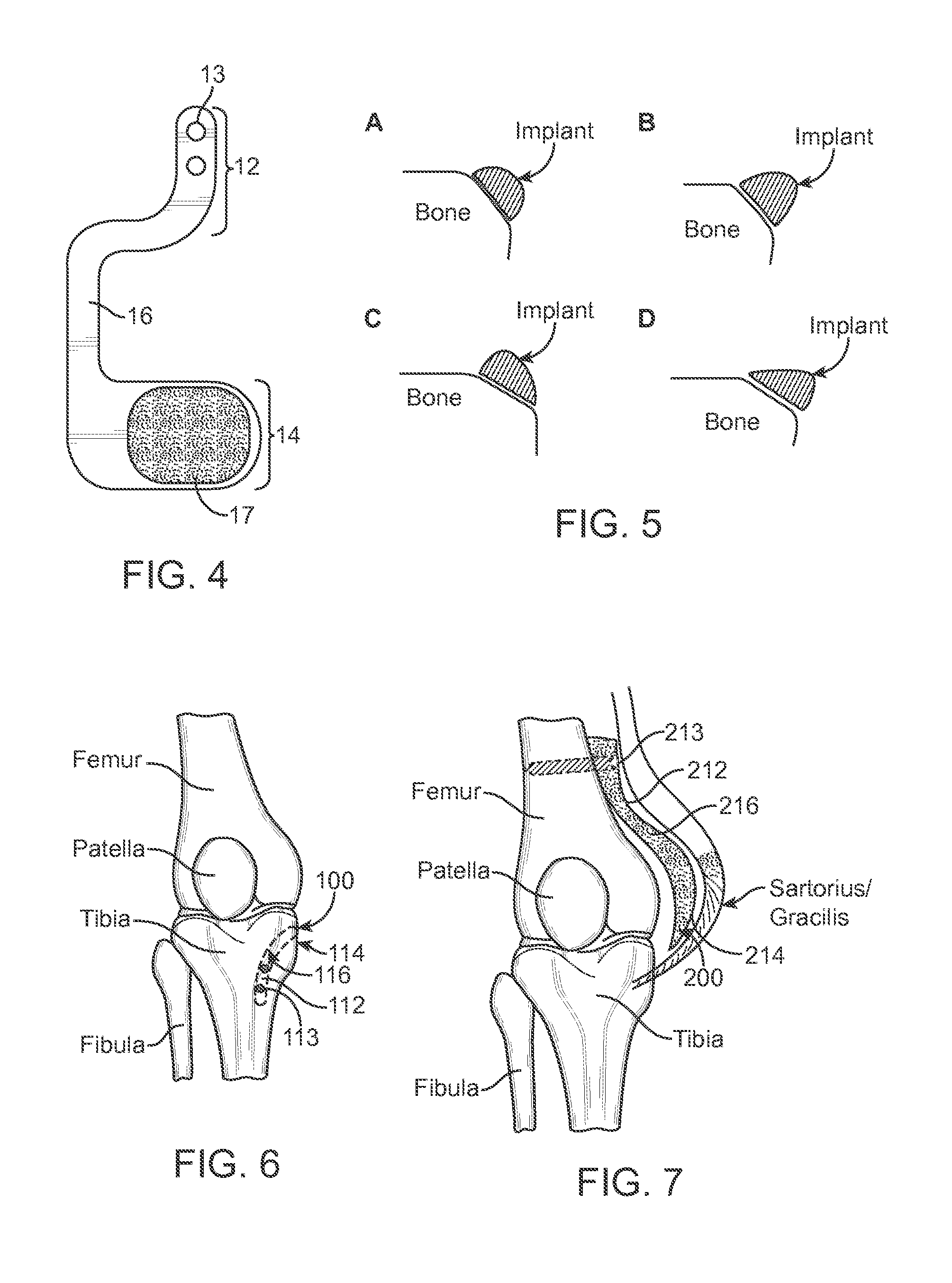
[0012]Exemplary methods disclosed herein comprise selecting at least one of the muscles and connective tissues associated with a joint as target tissue for treatment, and displacing the target tissue without severing the bones or target tissue, thereby redistributing loading in the joint to achieve a therapeutic effect.
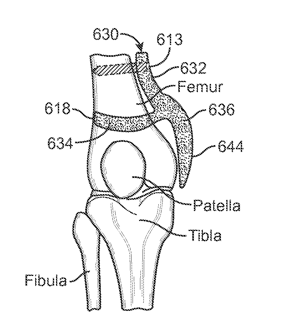
[0013]In exemplary embodiments, the target tissue is displaced by placing an implant in contact with the target tissue. The implant may be secured to a bone and / or to soft tissues, which may include the target tissue. In a preferred embodiment, the implant reduces a load in a joint that includes the same bone to which the implant is secured. For example, the implant may be secured to the femur in order to reduce a load on an articular surface of the femur in the medial or lateral compartments of the knee. In another embodiment, the implant may be secured to the femur to reduce a force exerted between the patella and the femur. In one exemplary embodiment, the implant is completely outside the capsule surrounding the joint.
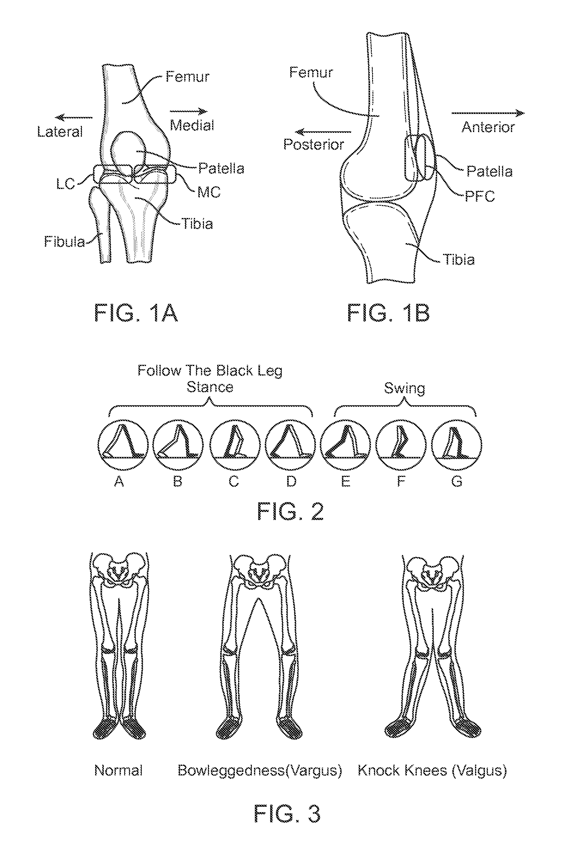
[0014]In some embodiments, the implant is secured on a first side of a joint to displace tissue on the first side of the joint in order to reduce a load on an opposing side of the joint. For example, the implant may be secured on a lateral side of the femur in order to reduce loads in the medial compartment of the knee. Or, the implant may be secured on a medial side of the femur to reduce loads in a lateral compartment of the knee.
[0016]In still further embodiments, connective tissue near a joint is displaced such that a moment arm through which the connective tissue acts upon the joint is increased, thereby reducing a load in the joint. An implant may be secured to a bone near the joint such that the implant displaces the connective tissue sufficiently to increase the moment arm.
[0027]Another exemplary method disclosed herein comprises selecting at least one of the associated muscle and connective tissues surrounding a joint as target tissue for treatment, displacing the target tissue without severing the bones or target tissue, thereby altering the kinematics of the joint to achieve a therapeutic effect. In some embodiments the kinematics are altered to redistribute loading in the joint to achieve the therapeutic effect. In other embodiments the kinematics are altered to reduce loading on the ligaments within the joint to achieve the therapeutic effect.
[0035]In some embodiments, an apparatus according to the invention comprises an implant configured to be anchored on the femur or tibia and configured to displace soft tissue so as to alter the kinematics of the knee joint. In some embodiments the kinematics are altered to redistribute loading in the joint to achieve the therapeutic effect. In other embodiments the kinematics are altered to reduce loading on the ligaments within the joint to achieve the therapeutic effect.
Problems solved by technology
When connective tissues are compromised, joint pain and loss of function can result.
Because the distal end of the femur is curved and asymmetric in shape, the knee joint not only flexes and extends like a hinge, but it also slides and rotates during flexion, resulting in a complex motion for the joint.
Over time, the cartilage may wear away entirely, resulting in bone-on-bone contact.
Since bones, unlike cartilage, have many nerve cells, direct bone contact can be very painful to the OA sufferer.
In addition to the pain and swelling, the OA sufferer can experience a progressive loss of mobility at the knee joint.
This is due to loss of the joint space, where the articular cartilage has completely worn away.
In patients suffering from patellofemoral OA, excessive compressive forces on the patello-femoral cartilage can cause pain and cartilage degeneration.
Such excessive compressive forces are often generated during stair climbing.
However, since articular cartilage is avascular, or lacks a blood supply, repair and growth of adult cartilage is minimal.
If the pain or immobility becomes too severe and other therapies do not alleviate the symptoms, surgical interventions become necessary.
Method used
Image
Click on the blue label to locate the original text in one second.
Reading with bidirectional positioning of images and text.
Examples
example
[0124]An exemplary embodiment of the present invention as shown in FIGS. 18A-D was subjected to simulated load testing. Dimensions of the implant tested were: W1=23 mm, W2=50 mm, LA=35 mm, LB=40 mm, D=30 mm. The test was conducted as follows: Using a robotic testing system for evaluating knee joint biomechanics, as described by Gadikota et al., American Journal of Sports Medicine, 38, 713-720, 2010, simulations were run using cadaveric human knee specimens. Eight fresh-frozen cadaveric human knee specimens (4 male, 4 female, Age: 36-50 y) stored at −20° C. were thawed at room temperature prior to testing. The quadriceps muscles were loaded at 300N, the hamstrings at 100N, and the iliotibial band at 0, 50, and 100N to simulate a variety of loading conditions. The displacement of the IT Band ranged from 15 to 20 mm. The robotic testing system was used to determine knee joint kinematics and contact forces in the medial and lateral compartments from 0° to 30° flexion, with and without t...
PUM
Abstract
Pathology of the human knee can arise from excessive and / or uneven loading of regions within the joint. Methods and apparatus are disclosed that enable displacement of soft tissue around the knee, without displacing or severing bone thereby altering the mechanical load distribution within the joint in a less invasive manner than previous techniques.
Description
RELATED APPLICATIONS[0001]This application is a continuation application of U.S. Nonprovisional patent application Ser. No. 13 / 843,128, filed on Mar. 15, 2013; which application was a nonprovisional of and claims priority to U.S. Provisional Patent Application Ser. No. 61 / 620,756 filed on Apr. 5, 2012 and U.S. Provisional Patent Application Ser. No. 61 / 695,406 filed on Aug. 31, 2012; U.S. Nonprovisional patent application Ser. No. 13 / 843,128 was also a Continuation-in-Part of U.S. Nonprovisional patent application Ser. No. 12 / 870,462, filed on Aug. 27, 2010 (now U.S. Pat. No. 8,597,362), which claims priority to U.S. Provisional Patent Application Ser. No. 61 / 237,518, filed Aug. 27, 2009, and U.S. Provisional Patent Application Ser. No. 61 / 288,692, filed Dec. 21, 2009. Each of these applications is incorporated herein by reference in its entirety. This application is also related to U.S. Nonprovisional patent application Ser. No. 13 / 002,829 filed on Aug. 27, 2010.FIELD OF THE INVENT...
Claims
Application Information
Patent Timeline
Application Date:The date an application was filed.
Publication Date:The date a patent or application was officially published.
First Publication Date:The earliest publication date of a patent with the same application number.
Issue Date:Publication date of the patent grant document.
PCT Entry Date:The Entry date of PCT National Phase.
Estimated Expiry Date:The statutory expiry date of a patent right according to the Patent Law, and it is the longest term of protection that the patent right can achieve without the termination of the patent right due to other reasons(Term extension factor has been taken into account ).
Invalid Date:Actual expiry date is based on effective date or publication date of legal transaction data of invalid patent.
Patent Type & AuthorityApplications(United States)

