Adapter for Power Tools, Power Tool System and Method of Operating the Same

a technology for adapters and power tools, applied in adaptive control, testing/monitoring control systems, instruments, etc., can solve the problem that adapters cannot be easily dislodged from power tools during operation, and achieve the effect of robust and durable structur

Active Publication Date: 2014-06-12
MAKITA CORP
View PDF11 Cites 110 Cited by
  • Summary
  • Abstract
  • Description
  • Claims
  • Application Information

AI Technical Summary

Benefits of technology

[0016]In such an arrangement, the adapter is not required to contain wiring for conducting current between the battery pack and the power tool, thereby minimizing space and manufacturing requirements. In addition or in the alternative, the adapter can be adapted or configured to be more firmly or fixedly attached to the power tool than conventional adapters, so that the adapter will not be readily dislodged from the power tool during operation.
[0027]Power tools according to this aspect of the present teachings can be manufactured with a base set of electrical functions and then the user can easily select one or more additional electronic functions to add to the power tool by attaching the appropriate adapter (i.e. an adapter equipped with the desired functionality). In particular, the detachable adapter may communicate one or more of the above-mentioned types of maintenance information concerning the power tool.
[0034]If the adapter of the above-noted aspect is at least partially disposed, located or accommodated between the housing and the battery pack, the embedded portion of the adapter is physically protected by the housing and / or the battery pack, e.g. when the hand-held power tool is dropped or bumps against something. Thus, this aspect of the present teachings provides a robust and durable structure for protecting the adapter in rugged work environments.

Problems solved by technology

In addition or in the alternative, the adapter can be adapted or configured to be more firmly or fixedly attached to the power tool than conventional adapters, so that the adapter will not be readily dislodged from the power tool during operation.

Method used


Image

  • Adapter for Power Tools, Power Tool System and Method of Operating the Same
  • Adapter for Power Tools, Power Tool System and Method of Operating the Same
  • Adapter for Power Tools, Power Tool System and Method of Operating the Same

Examples


first exemplary embodiment

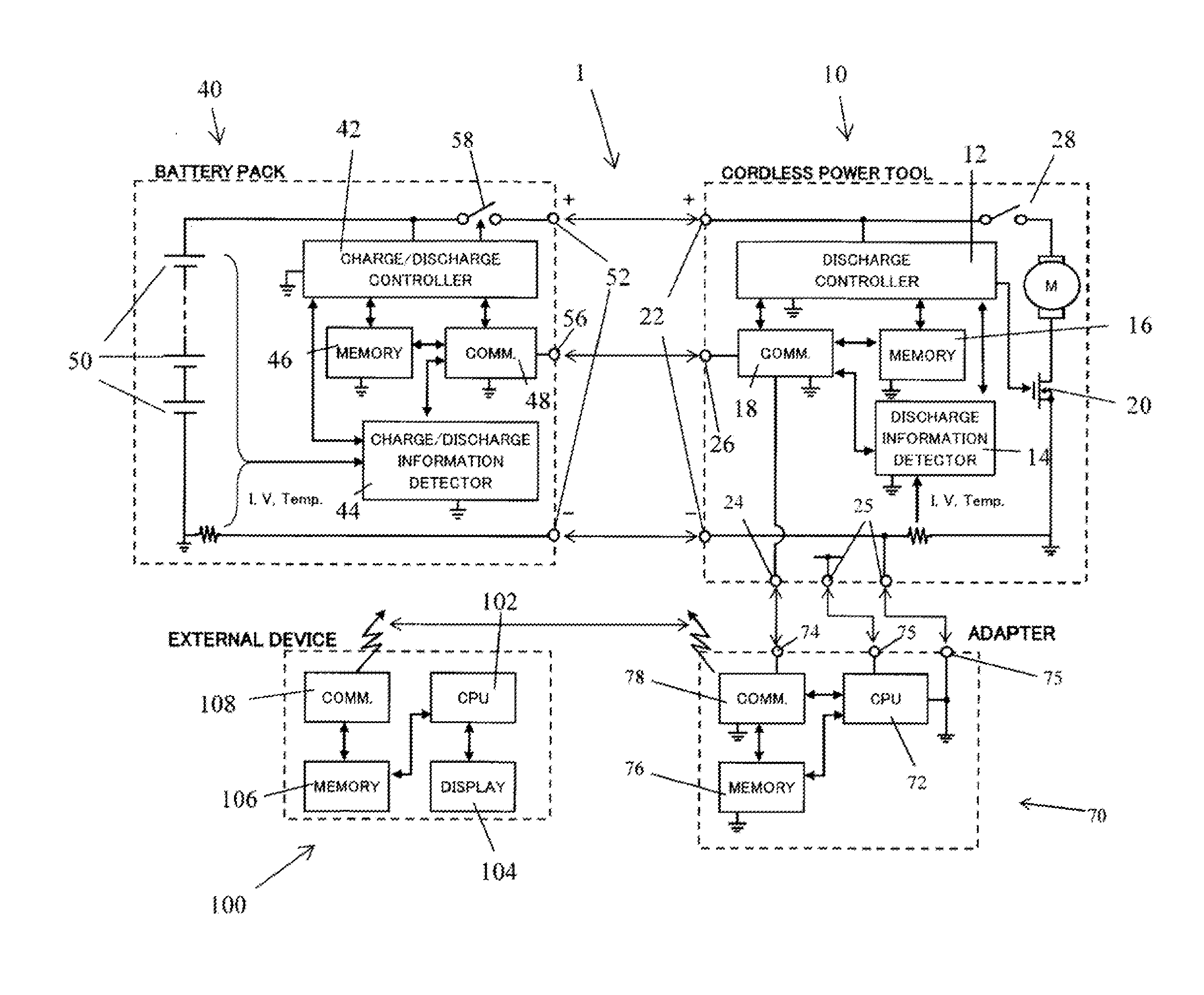
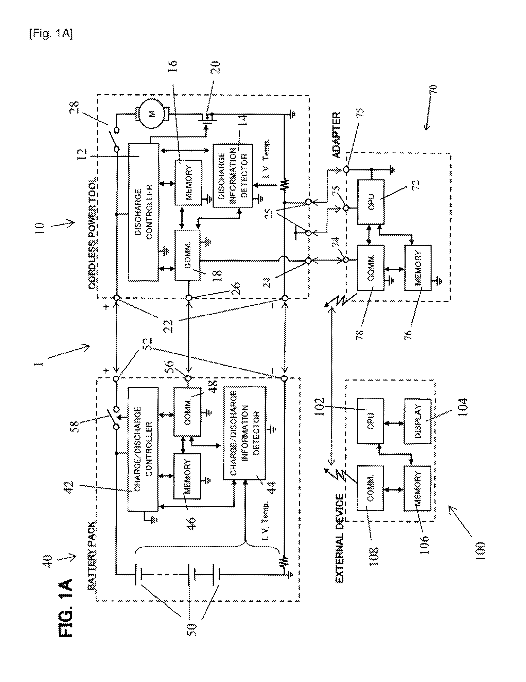
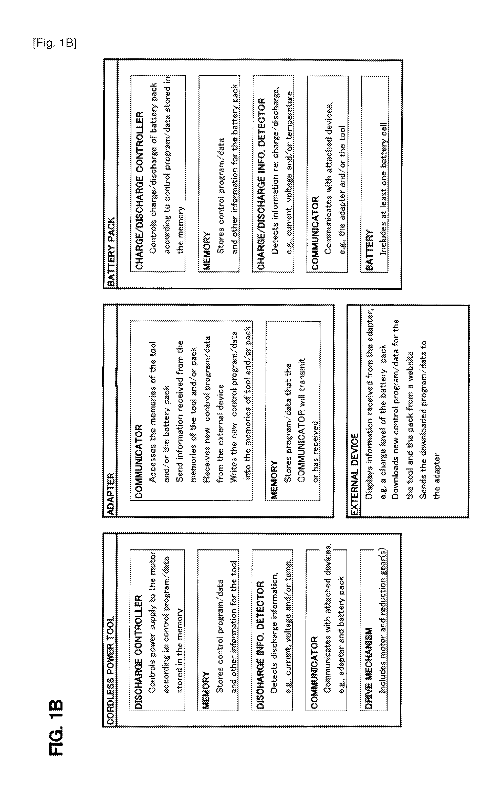
[0191]Referring to FIGS. 1A-1C, a first exemplary embodiment of a power tool system 1 according to the present teachings will now be described in further detail. The power tool system 1 may generally comprise a cordless (battery-powered) power tool 10, a battery pack 40, an adapter 70 and an external device 100.

[0192]The power tool 10 according to this exemplary embodiment generally comprises a controller 12, a discharge information detector 14, a memory 16 and a communicator 18. Power is supplied to the power tool 10 via two battery terminals 22 to drive the electric motor M by opening and closing power FET 20, e.g., utilizing a pulse-width modulation technique as is well known in the art. The operation of the motor M is manually controlled by a switch 28, which may be a trigger switch as is well known in the art. As shown in FIG. 1C, the motor M is enclosed in a housing 32 and drives a tool chuck 30, to which an appropriate tool, e.g., a screw bit, may be connected. A reduction ge...

second exemplary embodiment

[0207]The second exemplary embodiment shares many overlapping features, functions, circuits and structures with the first exemplary embodiment. Therefore, circuits and structures that operate in the same or substantially the same way have been assigned the same reference numbers and a further description thereof is not necessary. Reference is made to the first exemplary embodiment for any features, functions, circuits or structures that are not expressly described in the second exemplary embodiment, which are incorporated by reference into the present embodiment.

[0208]The power tool system 1′ of the second exemplary embodiment shown in FIG. 2A primarily differs from the first exemplary embodiment in that the adapter 70′ is configured to directly connect to the battery pack 40′, instead of directly connecting to the power tool 10′. The external device 100 communicates with the adapter 70′ and operates in the same way as the first embodiment.

[0209]Thus, in this exemplary embodiment, t...

third exemplary embodiment

[0214]The third exemplary embodiment also shares many overlapping features, functions, circuits and structures with the first and second exemplary embodiments. Therefore, circuits and structures that operate in the same or substantially the same way have been assigned the same reference numbers and a further description thereof is not necessary. Reference is made to the first or second exemplary embodiment for any features, functions, circuits or structures that are not expressly described in the third exemplary embodiment, which are incorporated by reference into the present embodiment.

[0215]The power tool system 1″ of the third exemplary embodiment shown in FIG. 3A primarily differs from the first and second exemplary embodiments in that the adapter 70″ is configured to directly connect to both the battery pack 40 and the power tool 10′. The external device 100 communicates with the adapter 70″ and operates in the same way as the first and second exemplary embodiments.

[0216]Thus, ...


PUM


Abstract

An adapter for a power tool powered by a detachable battery pack includes a connector for directly connecting the adapter only to the power tool in a detachable manner, a controller, at least one memory and / or storage device in communication with the controller, and at least one communication port configured to transmit electrical communications from the adapter controller to a controller located in the power tool and vice versa. The adapter is further configured such that, when a battery pack, which also includes a controller, is connected to the power tool, a communication path is established from the battery pack controller to the adapter controller via the power tool controller.

Description

CROSS-REFERENCE[0001]This application claims priority to U.S. Provisional Application No. 61 / 511,092 filed on Jul. 24, 2011, No. 61 / 564,513 filed on Nov. 29, 2011, No. 61 / 581,950 filed on Dec. 30, 2011, and No. 61 / 593,533 filed on Feb. 1, 2012, the contents of all of which are hereby incorporated by reference as if fully set forth herein.TECHNICAL FIELD[0002]The present invention generally relates to adapters for battery-powered power tools, e.g., hand-held power tools, which provide additional functionality, e.g., electrical functions, to the power tools and / or to the battery packs and / or to power tool systems including the same, as well as to power tool systems containing the adapters and methods of operating the same.BACKGROUND ART[0003]Electronic adapters for use with power tools are generally known in the art.[0004]For example, U.S. Pat. No. 7,357,526 discloses a power tool and accessory (adapter) combination. The power tool has multiple terminals to which a battery pack or bat...

Claims


Application Information

Patent Timeline
Patent Type & Authority Applications(United States)
IPC IPC(8): B25F5/00G05B13/02
CPCG05B13/024B25F5/00B25F5/02G08C17/02Y02E60/10H02J7/00B25F3/00H02J7/0042
Inventor FURUI, NOBUYASUSUZUKI, HITOSHIFUKUMOTO, MASAAKIUMEMURA, TAKUYAITO, KOSUKESENGIKU, HITOSHI
Owner MAKITA CORP
Why Eureka
Try Eureka