Image forming apparatus

Active Publication Date: 2014-06-12
CANON KK
View PDF4 Cites 2 Cited by
  • Summary
  • Abstract
  • Description
  • Claims
  • Application Information

AI Technical Summary

Benefits of technology

The technical effect of this patent is to improve the transfer of an image forming apparatus that uses a brush-typed transfer member, resulting in an improved image quality.

Problems solved by technology

If the position of the upstream end of the brush-typed transfer member is displaced from the contact area, there is a fear that an electric discharge might occur upstream of the contact area, degrading primary transfer property.
Consequently, even if the brush-typed transfer member is positioned accurately with respect to the contact area, positions at which the conductive filaments at the upstream end come into contact with the intermediate transfer belt might vary with respect to a direction orthogonal to the moving direction of the intermediate transfer belt, resulting in degradation of primary transfer property.
Note that, this problem occurs not only in the image forming apparatus which use an intermediate transfer belt as a transfer belt, but also in image forming apparatus which use a transport belt adapted to transport a transfer material, as a transfer belt.

Method used


Image

  • Image forming apparatus
  • Image forming apparatus
  • Image forming apparatus

Examples


first embodiment

1. Overall Configuration of Image Forming Apparatus

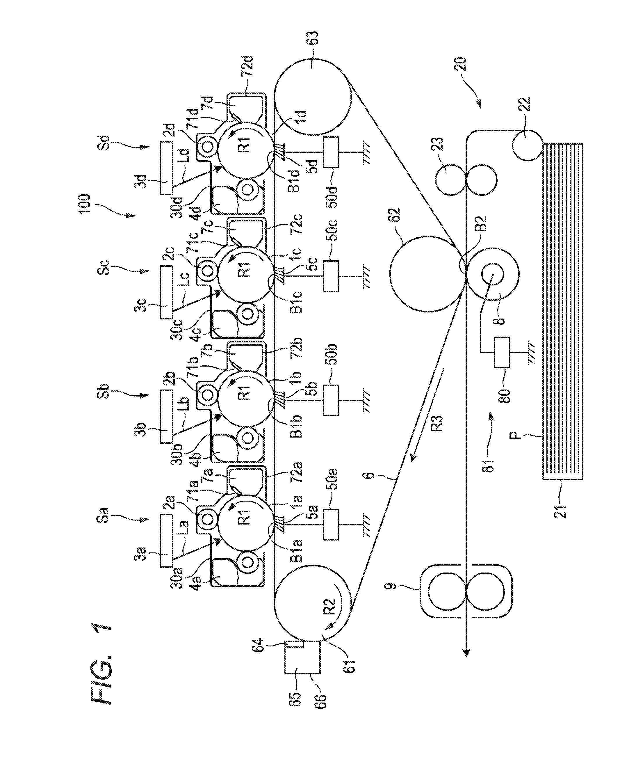
[0030]FIG. 1 is a schematic sectional view showing an overall configuration of an image forming apparatus according to a first embodiment of the present invention. The image forming apparatus 100 in accordance with the first embodiment is an electrophotographic full-color laser beam printer. Also, the image forming apparatus 100 is a tandem type which uses an intermediate transfer method. That is, the image forming apparatus 100 obtains a recorded image by forming toner images of different colors on respective image bearing members based on image information broken down into plural color components, primary-transferring the toner images one after another onto an intermediate transfer member, and secondary-transferring the toner images onto transfer material at once.

[0031]The image forming apparatus 100 has a first, second, third and fourth stations Sa, Sb, Sc and Sd as a plurality of image forming units. According to the first emb...

second embodiment

[0085]An image forming apparatus according to a second embodiment of the present invention will be described with reference to FIGS. 10 and 11. An upstream end geometry of the primary transfer brush 5 characteristic of the second embodiment will mainly be described here. Matters not described here particularly are matters similar to those of the first embodiment. The same components as those in the first embodiment are denoted by the same reference numerals as the corresponding components in the first embodiment, and description thereof will be omitted.

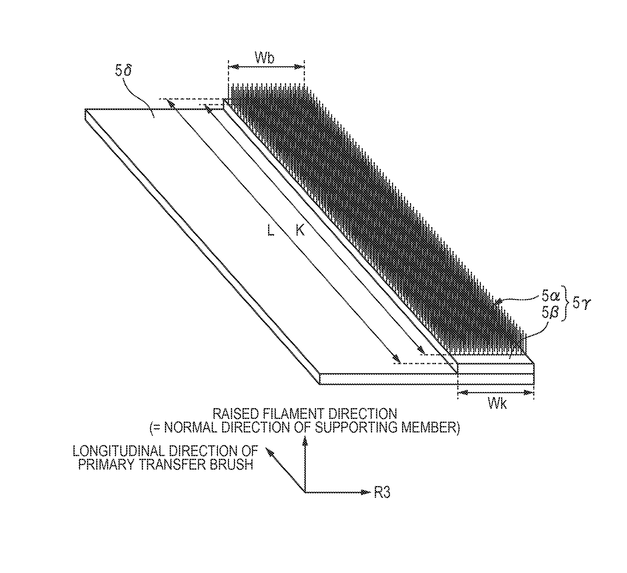
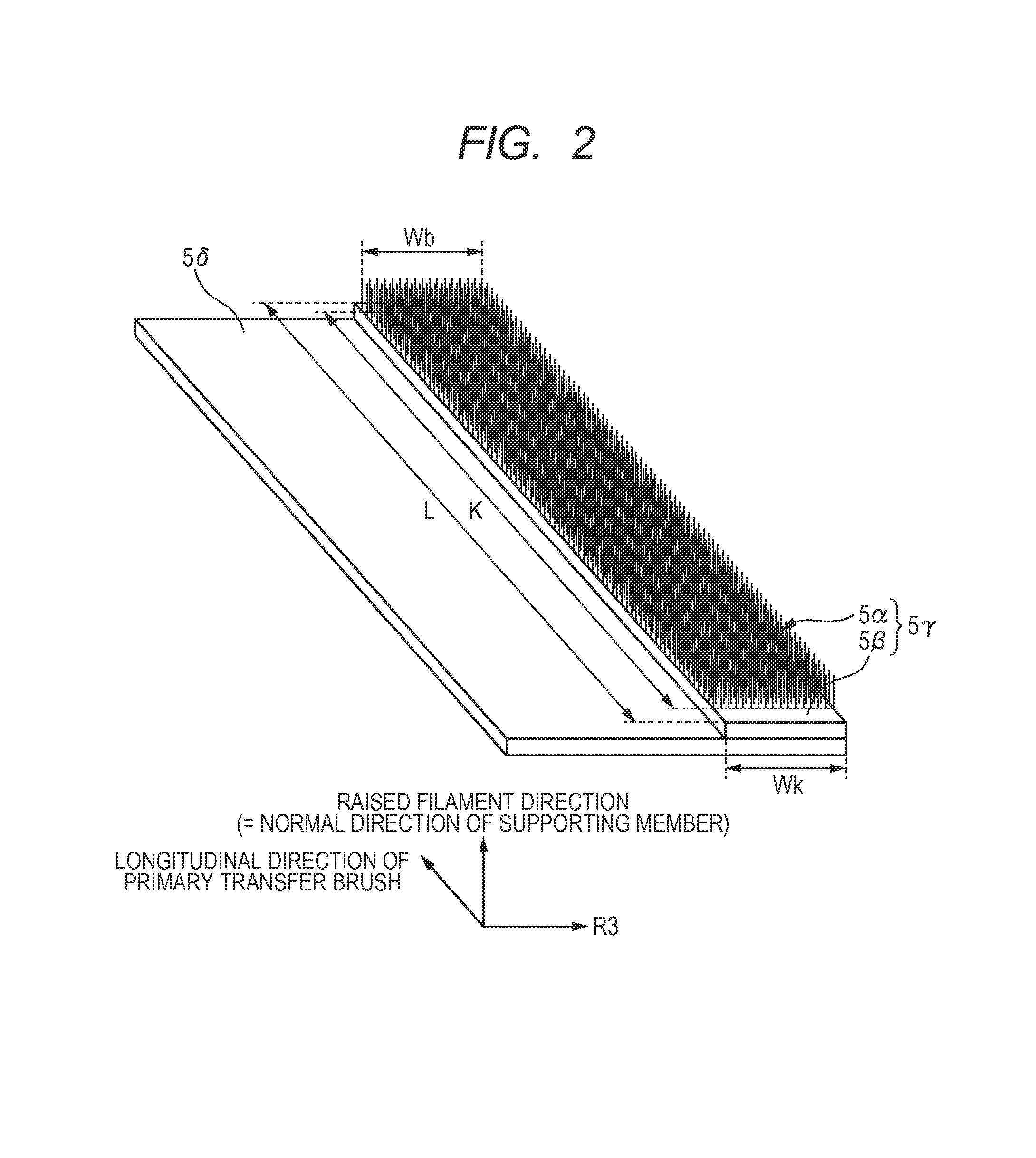
[0086]The primary transfer brush 5 used in the second embodiment is characterized in that the filaments in the raised filament portion 5α have been tilted in the moving direction of the intermediate transfer belt 6 and that the raised filament portion 5α and base fabric portion 5β have been cut such that the upstream end geometry of the primary transfer brush 5 will be rectilinear along the length of the primary transfer brush 5. This...

third embodiment

[0090]An image forming apparatus according to a third embodiment of the present invention will be described with reference to FIGS. 12 and 13. An upstream end geometry of the primary transfer brush 5 characteristic of the third embodiment will mainly be described here. Matters not described here particularly are matters similar to those of the embodiments described above. The same components as those in the above embodiments are denoted by the same reference numerals as the corresponding components in the above embodiments, and description thereof will be omitted.

[0091]FIG. 12 is an enlarged schematic diagram (perspective view) of the upstream end of the primary transfer brush 5 according to the third embodiment.

[0092]The raised filament portion 5α is bonded together such that the upstream end geometry of the primary transfer brush 5 used in the third embodiment will be substantially rectilinear along the length of the primary transfer brush 5. More particularly, in the third embodi...


PUM


Abstract

The image forming apparatus includes an image bearing member adapted to bear a toner image, a transfer belt configured to be movable, a transfer device placed across the transfer belt from the image bearing member and adapted to transfer the toner image from the image bearing member to the transfer belt, the transfer device including a brush member equipped with a plurality of conductive filaments to be put into contact with the belt, wherein the plurality of conductive filaments located at an upstream end in a moving direction of the transfer belt is cut along an orthogonal direction intersecting the moving direction of the transfer belt at right angles or the conductive filaments located at an upstream end of the brush member along the moving direction of the transfer belt are bonded together.

Description

BACKGROUND OF THE INVENTION[0001]1. Field of the Invention[0002]The present invention relates to an electrophotographic image forming apparatus.[0003]2. Description of the Related Art[0004]Conventional image forming apparatus such as copiers and printers which use an electrophotographic method include a type which uses an intermediate transfer belt. An image forming apparatus of an intermediate transfer belt type forms a full-color image through a primary transfer process and secondary transfer process. In the primary transfer process, a toner image formed on a surface of an electrophotographic photosensitive body is transferred onto the intermediate transfer belt. This process is repeated for toner images of plural colors, thereby forming toner images of the plural colors on the surface of the intermediate transfer belt. In the secondary transfer process, the toner images of the plural colors are transferred altogether onto a surface of a transfer material such as paper. The toner ...

Claims


Application Information

Patent Timeline
IPC IPC(8): G03G15/16
CPCG03G2215/1642G03G15/1685G03G15/1665
Inventor AKAMATSU, TAKAAKIOGAWA, KENICHIAN, KOJI
Owner CANON KK
Why Eureka
Try Eureka