Image forming apparatus

Pending Publication Date: 2022-11-10
CANON KK
View PDF0 Cites 0 Cited by
  • Summary
  • Abstract
  • Description
  • Claims
  • Application Information

AI Technical Summary

Benefits of technology

[0010]Accordingly, an object of the present invention is to provide an image forming apparatus capable of realizing improvement in t

Problems solved by technology

For example, in the case where the recording material is “thin paper” which is an example of the recording material with small rigidity, in the neighborhood of the secondary transfer nip on the side downstream of the secondary transfer nip with respect to the recording material feeding direction, the intermediary transfer belt and the recording material stick to each other, so that a jam (paper jam) occurs in some instances due to improper separation of the recording material from the intermediary transfer belt.
This phenomenon becomes conspicuous in the case where the rigidity of the recording material is small because the recording material is liable to stick to the intermediary transfer belt due to weak stiffness of the recording material.
This phenomenon becomes conspicuous in the case where the rigidity of the recording material is large because the trailing end portion of the recording material with respect to the recording material feeding direction is liable to powerfully colli

Method used


Image

  • Image forming apparatus
  • Image forming apparatus
  • Image forming apparatus

Examples


Example

Embodiment 1

1. General Constitution and Operation of Image Forming Apparatus

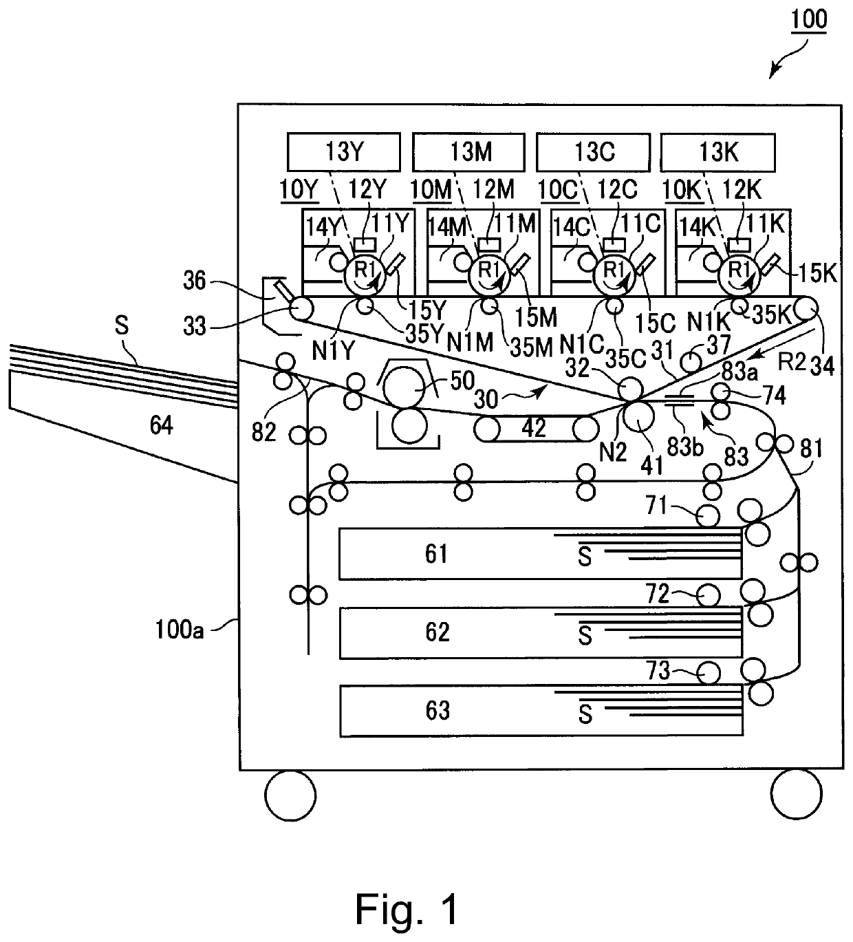
[0025]FIG. 1 is a schematic sectional view of an image forming apparatus 100 of the present invention. The image forming apparatus 100 of this embodiment is a tandem multi-function machine (having functions of a copying machine, a printer and a facsimile machine) employing an intermediary transfer type. For example, in accordance with an image signal sent from an external device, the image forming apparatus 100 is capable of forming a full-color image on a sheet-like recording material (a transfer material, a sheet material) S such as paper by using an electrophotographic type.

[0026]The image forming apparatus 100 includes, as a plurality of image forming portions (stations), four image forming portions 10Y, 10M, 10C and 10K for forming images of yellow (Y), magenta (M), cyan (C) and black (K), respectively. These image forming portions 10Y, 10M, 10C and 10K are disposed in series along a movement direction ...

Example

Embodiment 2

[0099]Next, another embodiment of the present invention will be described. Basic constitutions and operations of an image forming apparatus in this embodiment are the same as those of the image forming apparatus in the embodiment 1. Accordingly, elements having the same or corresponding functions or constitutions as those in the image forming apparatus of the embodiment 1 are represented by the same reference numerals or symbols as those in the embodiment 1 and will be omitted from detailed description.

[0100]In the embodiment 1, in the case where the offset amount X is changed during execution of the mixed job, when the inner roller 32 is moved, the intermediary transfer belt 31 was rotated at a driving speed (peripheral speed) during normal image formation.

[0101]However, the inner roller 32 moved in the offset operation is one of the plurality of rollers stretching the intermediary transfer belt 31, and therefore, the movement of the inner roller 32 has the influence on...

Example

Embodiment 3

[0112]Next, another embodiment of the present invention will be described. Basic constitutions and operations of an image forming apparatus in this embodiment are the same as those of the image forming apparatus in the embodiment 1. Accordingly, elements having the same or corresponding functions or constitutions as those in the image forming apparatus of the embodiment 1 are represented by the same reference numerals or symbols as those in the embodiment 1 and will be omitted from detailed description.

[0113]In the embodiment 1, the case where the offset amount X is changed by changing the position of the inner roller 32 was described. In this embodiment, the case where the offset amount X is changed by changing the position of the outer roller 41 will be described. In the embodiment 1, the outer roller 41 may only be required to be moved relative to the inner roller 32 toward a downstream side with respect to the rotational direction of the intermediary transfer belt 31...


PUM


Abstract

An image forming apparatus 100, employs a constitution in which in a case that a relative position between an inner roller 32 and an outer member 41 with respect to a circumferential direction of the inner roller 32 is changed in a period after a preceding recording material S passed through a transfer portion N2 and until the recording material S subsequent to the preceding recording material S reaches the transfer portion N2 device execution of a job for forming and outputting images on a plurality of recording materials S, a controller 150 controls a position changing mechanism 1 so that the above-described relative position is changed in a state in which the outer member 41 contacts the intermediary transfer belt 31.

Description

TECHNICAL FIELD[0001]The present invention relates to an image forming apparatus, such as a copying machine, a printer or a facsimile machine, using an electrophotographic type or an electrostatic recording type.BACKGROUND ART[0002]Conventionally, as the image forming apparatus using the electrophotographic type, there is an image forming apparatus using an endless belt (hereinafter, also simply referred to as a “belt”) as an image bearing member for bearing a toner image. As such a belt, for example, there is an intermediary transfer belt used as a second image bearing member for feeding the toner image primary-transferred from a photosensitive member or the like as a first image bearing member, in order to secondary-transfer the toner image onto a sheet-like recording material such as paper. In the following, principally, an image forming apparatus employing an intermediary transfer type including an intermediary transfer belt will be described as an example.[0003]In the image for...

Claims


Application Information

Patent Timeline
IPC IPC(8): G03G15/16
CPCG03G15/1615
Inventor TANIGUCHI, KOICHI
Owner CANON KK
Why Eureka
Try Eureka