

Image recording apparatus
- Summary
- Abstract
- Description
- Claims
- Application Information
AI Technical Summary
Benefits of technology
Problems solved by technology
Method used
Image

Examples
first embodiment
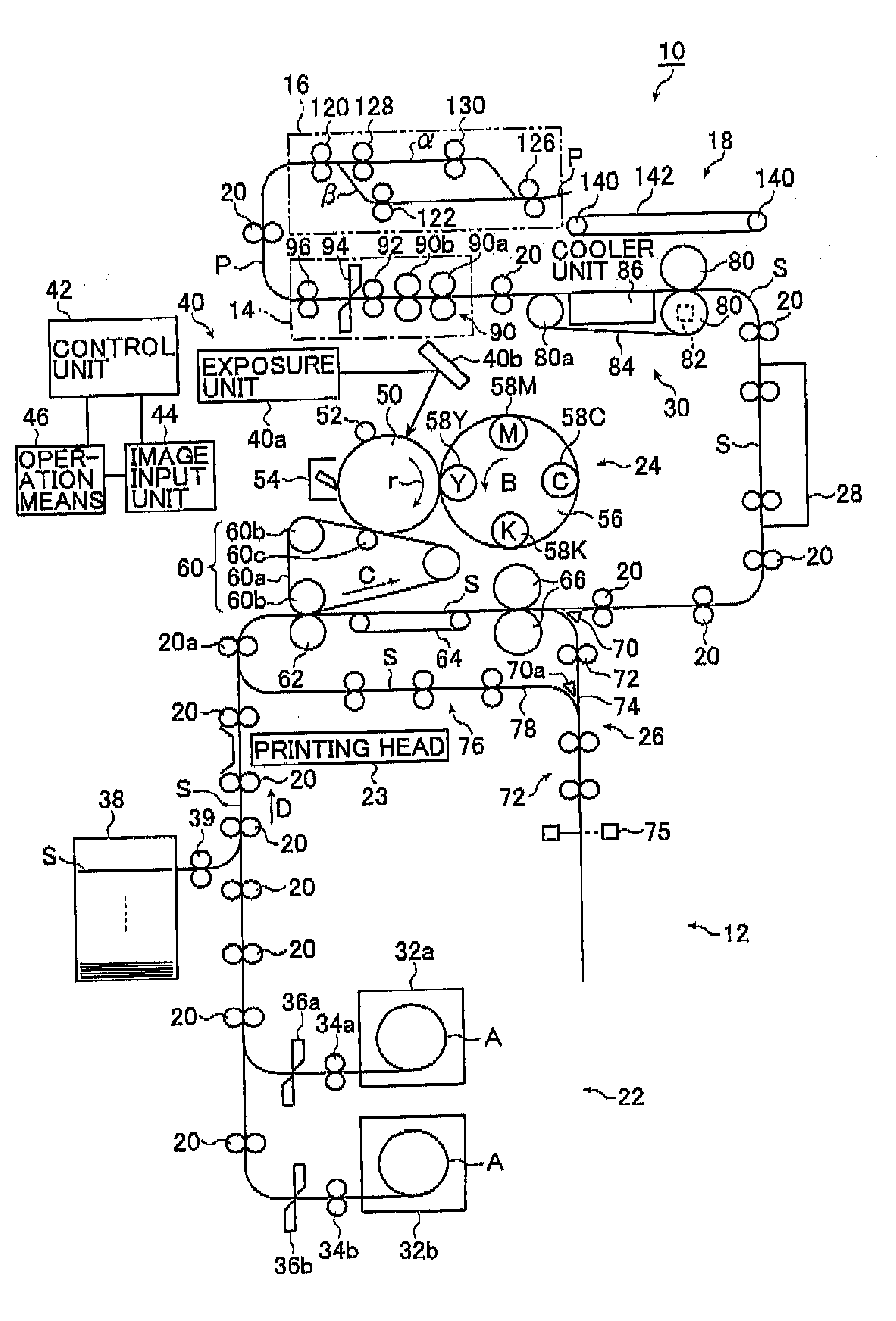
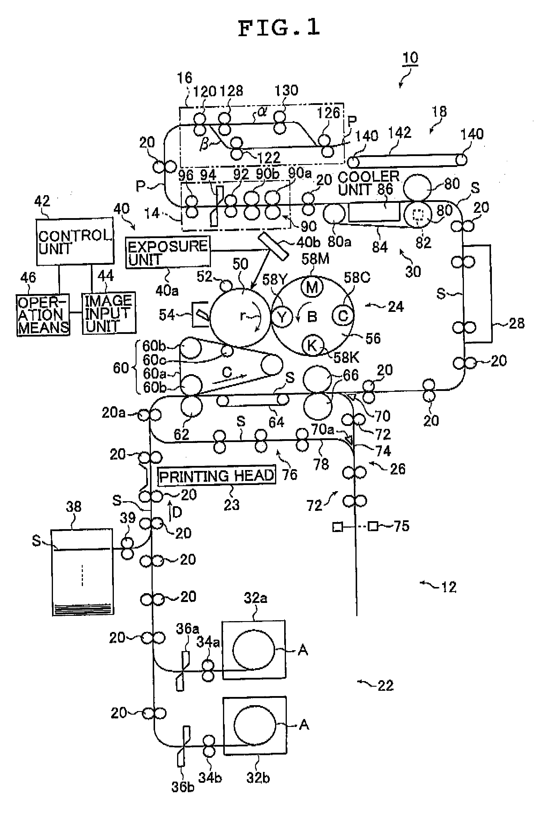
[0091]FIG. 1 is a schematic diagram for indicating one embodiment (hereinafter referred to as “first embodiment”) of the image recording apparatus according to the first aspect of the present invention.
[0092] As indicated in FIG. 1, an image recording apparatus 10 of the first embodiment comprises an image recording section 12, a cutting section 14, a shifter section 16 which functions as an arranging section, a sort transporting section 18, and transporting means comprising transporting rollers 20.
[0093] The image recording section 12 is connected to the cutting section 14, the cutting section 14 is connected to the shifter section 16, and the shifter section 16 is connected to the sort transporting section 18, by the transporting means comprising the transporting rollers 20. In other words, the respective structural elements of the image recording section 12, the cutting section 14, the shifter section 16, and the sort transporting section 18 comprise transporting means including...
second embodiment
[0314]FIG. 16 is a schematic diagram for indicating one embodiment (hereinafter referred to as “second embodiment”) of the image recording apparatus according to the second aspect of the present invention.
[0315] It should be noted that because an image recording apparatus 10a of the second embodiment shown in FIG. 16 has a similar arrangement to the above-mentioned image recording apparatus 10 of the first embodiment shown in FIG. 1 except for the following different technical points, the same reference numerals of the image recording apparatus 10 will be employed as those for denoting the same structural elements, and detailed descriptions thereof are omitted. Therefore, different points will be mainly explained. That is, instead of the control unit 42, a control unit 47 is employed, and accordingly, control operations as to the shifter section 16 and the sort transporting section 18 are different, and as a result, functions and operations thereof are different from those of the im...
third embodiment
[0432]FIG. 37 is a schematic diagram for indicating one embodiment (hereinafter referred to as “third embodiment”) of the image recording apparatus according to the third aspect of the present invention.
[0433] It should be noted that the image recording apparatus 10b of the third embodiment shown in FIG. 37 has a similar structure to the above-mentioned image recording apparatus 10a of the second embodiment shown in FIG. 16 except for the following points. The same reference symbols of the image recording apparatus 10a will be employed as those for denoting the same structural elements of the image recording apparatus 10b, and detailed descriptions thereof are omitted. Therefore, different points will be mainly explained. That is, instead of the control unit 47 and the sort transporting section 18, a control unit 48 and a sort transporting section 19 are employed.
[0434] As indicated in FIG. 37, the image recording apparatus 10b of the third embodiment comprises the image recording ...
PUM
 Abstract
Description
Claims
Application Information