Machine tool with lathe tool and scraping cutter

a technology of scraping cutter and machine tool, which is applied in the field of machine tools, can solve the problems of reducing the scraping process efficiency, difficult to machine tool a surface not made for rotating, and inconvenient to machine the peripheral sidewall of the lath

Active Publication Date: 2014-06-19
FU DING ELECTRONICSAL TECH JIASHAN +1
View PDF26 Cites 14 Cited by
  • Summary
  • Abstract
  • Description
  • Claims
  • Application Information

AI Technical Summary

Problems solved by technology

Then a polishing process needs to be applied for a better appearance, thus the efficiency of the scraping process is reduced.
If a lathe process is adopted to machine the metallic member, it is difficult to machine tool a surface which is not made for rotating.
The lathe is not suitable to machine the peripheral sidewalls because of the four corners of the peripheral sidewall.

Method used


Image

  • Machine tool with lathe tool and scraping cutter
  • Machine tool with lathe tool and scraping cutter
  • Machine tool with lathe tool and scraping cutter

Examples


first embodiment

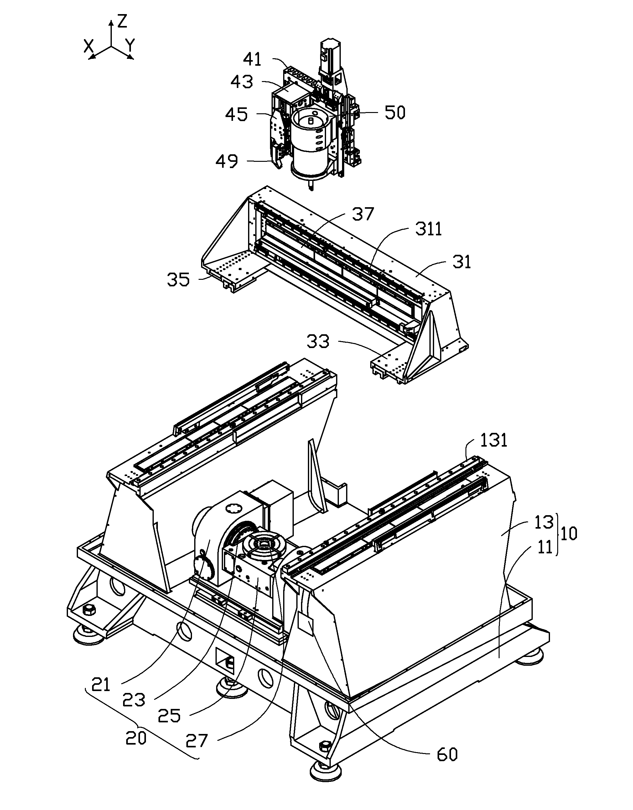
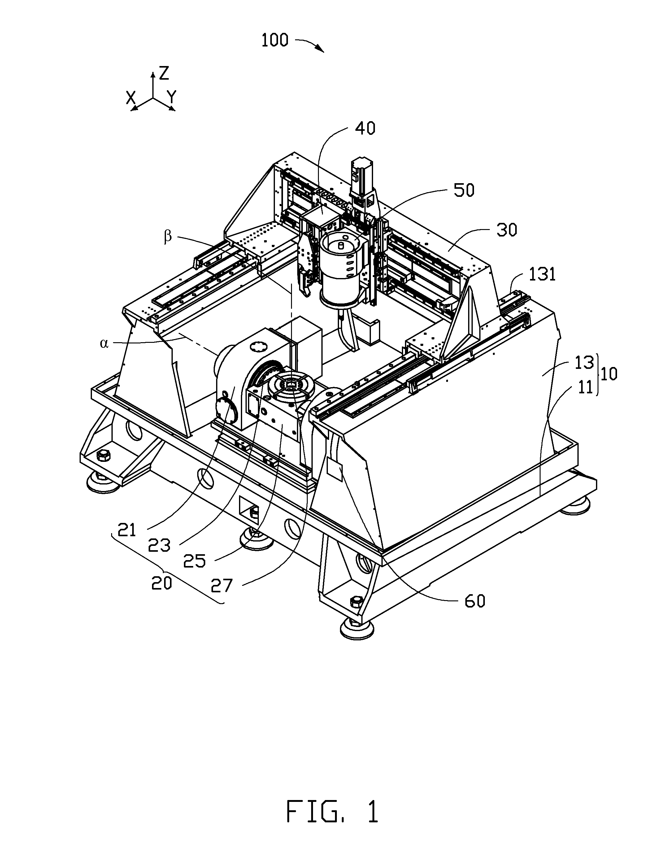
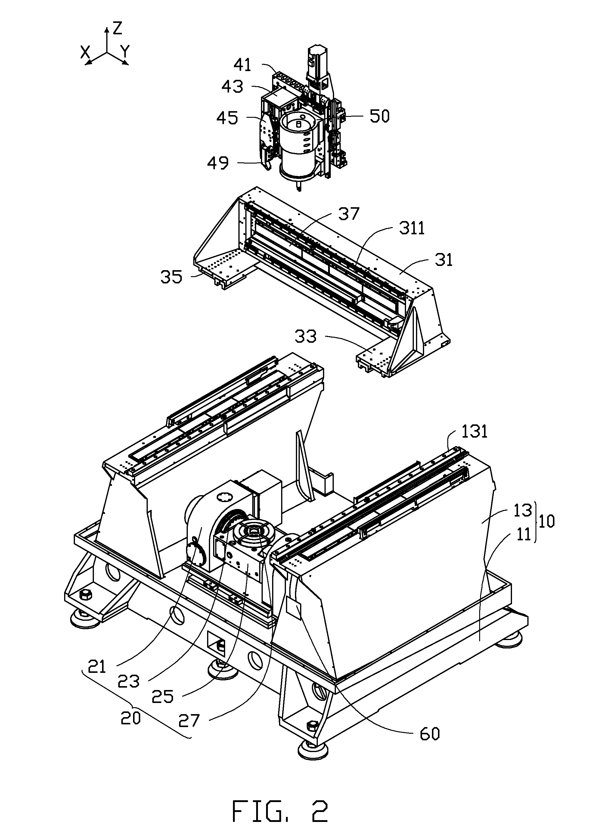
[0015]FIGS. 1 and 2 show a machine tool 100 for machining a metallic member 300 (see FIG. 5). The machine tool 100 includes a machine support 10, a worktable 20, a moving device 30, a lathe feeding mechanism 40, a scraping feeding mechanism 50, and a controller 60. The worktable 20 holds a workpiece in place and is supported by the machine support 10. The moving device 30 is movably positioned on the machine support 10 above the worktable 20. The lathe feeding mechanism 40 and the scraping feeding mechanism 50 are arranged side by side and slidably mounted on the moving device 30. The controller 60 is electrically connected to the worktable 20, the moving device 30, the lathe feeding mechanism 40, and the scraping feeding mechanism 50 for controlling the machine tool 100. Under the control of the controller 60, the moving device 30 can be driven to move with the lathe feeding mechanism 40 and the scraping feeding mechanism 50, such that the lathe feeding mechanism 40 and the scrapin...

second embodiment

[0036]FIG. 7 shows machine tool 200 for machining the metallic member 300. The machine tool 200 is similar to the machine tool 100 in structure, a sliding saddle 41a is slidably assembled to a cross beam 31a, and a second rotating member 27a is mounted on a rotating shaft 25a. The metallic member 300 is placed and held on the second rotating member 27a. The difference between the machine tool 100 / 200 is that, a mounting seat 43a of the machine tool 200 is slidably mounted on the sliding saddle 41a and capable of sliding along the Z1-axis direction relative to the sliding saddle 41a, and a lathe tool 49a is slidably mounted on the mounting seat 43a.

[0037]When the lathe feeding mechanism 40 is used to machine the top portion 301 of the metallic member 300, the pair of first driving mechanisms 35 drives the cross beam 31 to slide along the X-axis, and the second driving mechanism 37 drives the lathe feeding mechanism 40 to move along the Y-axis. In such a way that the lathe tool 49a a...


PUM

PropertyMeasurementUnit
metallicaaaaaaaaaa
surface areaaaaaaaaaaa
speedaaaaaaaaaa

Abstract

A machine tool with lathe tool and scraping cutter includes a machine support, a worktable, a moving device, a lathe feeding mechanism and a scraping feeding mechanism. The worktable is positioned on the machine support. The moving device is slidably assembled to the machine support along a first direction and located above the worktable. The lathe feeding mechanism and the scraping feeding mechanism are slidably assembled to the moving device along a second direction perpendicular to the first direction, the lathe feeding mechanism includes a feeding assembly and a lathe tool connected to the feeding assembly, the feeding assembly is configured for driving the lathe tool to move along a third direction substantially perpendicular to the first and second direction reciprocally, the scraping feeding mechanism includes a scraping cutter and is configured for driving the scraping cutter to move along the third direction.

Description

CROSS-REFERENCE TO RELATED APPLICATIONS[0001]This application claims all benefits accruing under 35 U.S.C. §119 from China Patent Application No. 201210554346.7, filed on Dec. 19, 2012, in the China Intellectual Property Office, the disclosure of which is incorporated herein by reference. The application is also related to co-pending applications entitled, “METHOD FOR MACHINING METALLIC MEMBER USING LATHING AND MILLING” (Atty. Docket No. US49872); “METHOD FOR MACHINING METALLIC MEMBER USING LATHING AND MILLING” (Atty. Docket No. US50023); “METHOD FOR MACHINING METALLIC MEMBER USING LATHING AND SCRAPING” (Atty. Docket No. US50024); “METHOD FOR MACHINING METALLIC MEMBER USING LATHING AND SCRAPING” (Atty. Docket No. US50025); “METHOD FOR MACHINING METALLIC MEMBER USING LATHING AND SCRAPING” (Atty. Docket No. US50026); “MACHINE TOOL WITH LATHE TOOL AND MILLING CUTTER” (Atty. Docket No. US50027); “MACHINE CONTROL SYSTEM EMPLOYING LATHE TOOL AND MILLING CUTTER”(Atty. Docket No. US50030), ...

Claims


Application Information

Patent Timeline
Patent Type & Authority Applications(United States)
IPC IPC(8): B23P23/02
CPCB23B3/00B23P23/02B23B3/065B23B5/36Y10T409/305824Y10T29/5109B23Q39/024Y10T29/5176B23D11/00B23Q2039/008B23Q1/26B23Q5/38B23Q5/40B23Q2705/10Y10T29/5114Y10T29/5115Y10T82/2511Y10T82/2535Y10T82/2541Y10T82/2566Y10T409/500164Y10T409/50246Y10T409/506232Y10T409/508036B23B3/10B23D1/10B23D5/00B23D7/02B23D7/04B23D7/06B23D7/08B23D79/02B23Q1/012B23Q1/017B23Q1/5406B23Q1/626B23Q5/28B23Q2220/004B23Q2230/004B23Q2701/01B23Q2701/025B23Q2705/102B23Q2705/106B23Q2705/14
Inventor YANG, MING-LUZHANG, TIAN-ENZHANG, WEI-CHUANJIA, JIAN-SHIPENG, YANG-MAOQU, JIANCHEN, FENG-HUAXU, ZHEN-GUANGSUI, JING-SHUANGZHUANG, DA-QINGLI, JIELIU, YIYU, JIAN-MIN
Owner FU DING ELECTRONICSAL TECH JIASHAN
Why Eureka
Try Eureka