Foil composite card

a composite card and composite material technology, applied in the field of composite card manufacturing, can solve the problems of easy and inadvertent scratching or marring, card and/or hologram distortion, and counterfeiters' inability to alter the card

Active Publication Date: 2014-06-19
COMPOSECURE LLC
View PDF6 Cites 33 Cited by
  • Summary
  • Abstract
  • Description
  • Claims
  • Application Information

AI Technical Summary

Benefits of technology

[0008]A hologram may be formed by embossing a designated area of the core layer with a diffraction pattern and vapor depositing a very thin layer of metal or metal compound (e.g., aluminum, zinc sulfide, etc . . . ) on the embossed layer. Then, additional layers are selectively attached to the top and bottom surfaces of the core layer. In accordance with the invention, for each additional layer attached to the top surface of the core layer there is a corresponding like layer attached to the bottom surface of the core layer for producing a highly symmetrical structure (sandwich).
[0011]After the hologram is formed, a laser may be used to remove selected portions of the metal formed on the embossed layer to impart a selected pattern or information to the holographic region. In accordance with the invention, this step in making a card or a set of cards may be performed when the card or cards being processed are attached to, and part of, a large sheet of material, whereby the “lasering” of all the cards on the sheet can be done at the same time and relatively inexpensively.
[0013]Embodiments of the invention may include the use of a polyester film, or any other carrier, which includes a metallic or a high refractive index (HRI) transparent holographic foil that is pre-laminated between two sheets of a material (which could be PVC, PET or other thermo-plastic resin) that has a thermo-plastic adhesive (which may have, but not necessarily has, been previously applied). The pre-laminated holographic foil can have an unlimited number of patterns and may also be configured to include one, or several individual, hologram designs repeated in rows and columns across an entire sheet. The holographic design may also have the appearance of full metal, or partial metal and partial white coverage (white reflecting hologram) on each individual card in the matrix. Utilizing this holographic foil pre-laminate in concert with standard plastic card materials, enables a plastic card manufacturer to produce “full-face” foil pattern design cards, or “full-face” registered hologram cards.

Problems solved by technology

A disadvantage to so placing the holograms is that a counterfeiter may be able to alter the card without the tampering being readily apparent to someone examining or accepting the card.
Also, positioning the hologram close to the top or the bottom surface of the card creates an asymmetry in its construction, whereby, when the temperature varies, different portions (layers) of the card may be placed under different degrees of tension and contraction resulting in stresses which tend to distort the card and / or the hologram (e.g., the card fails to remain flat).
Still further, when the hologram is placed at, or near, the top or the bottom surfaces it may be easily and inadvertently scratched or marred.

Method used


Image

  • Foil composite card
  • Foil composite card
  • Foil composite card

Examples


Embodiment Construction

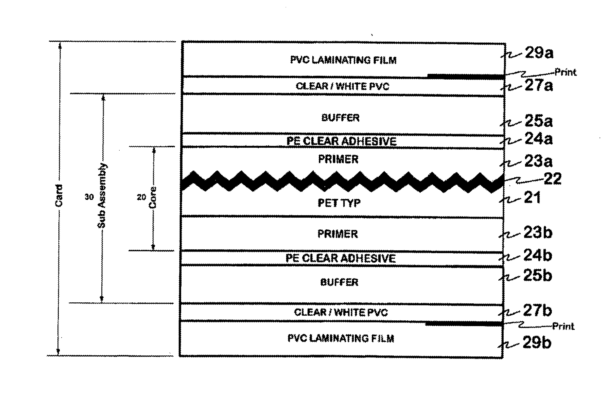
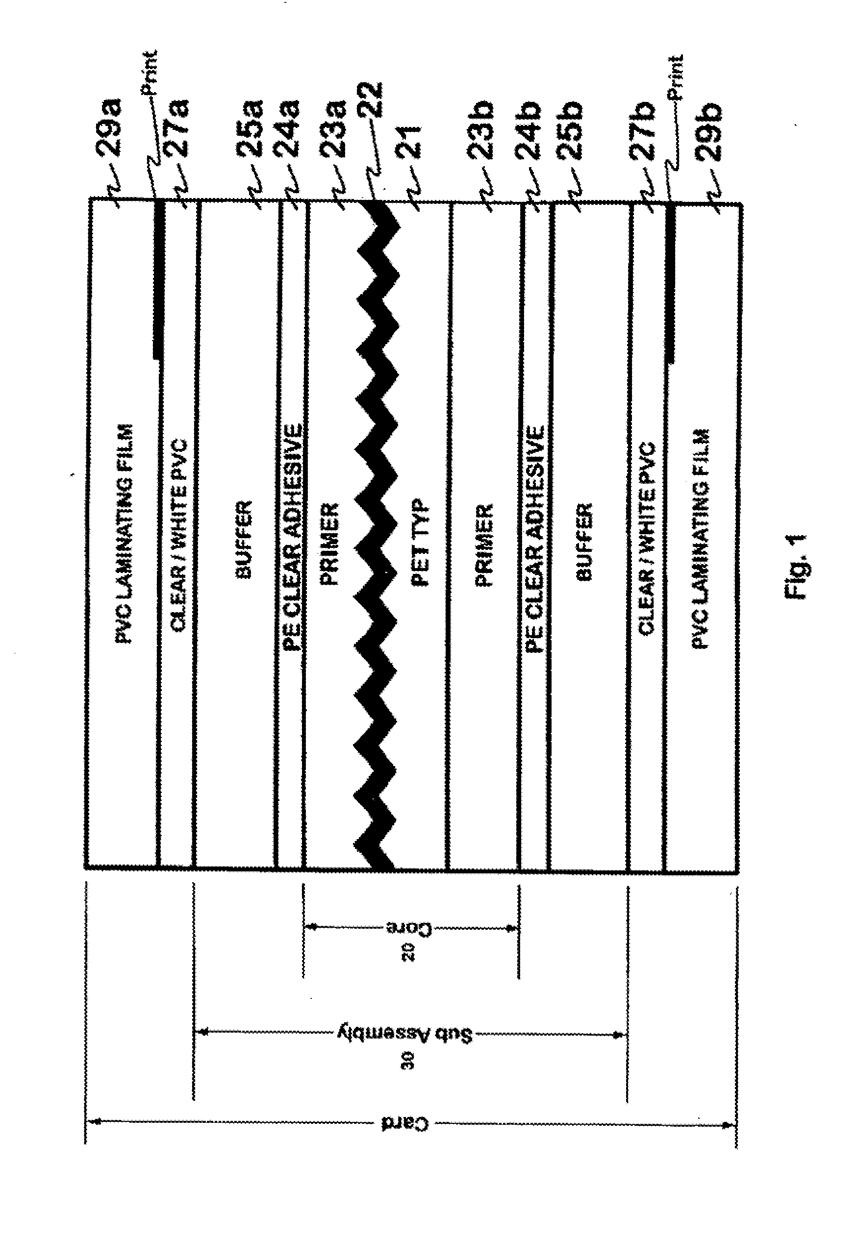
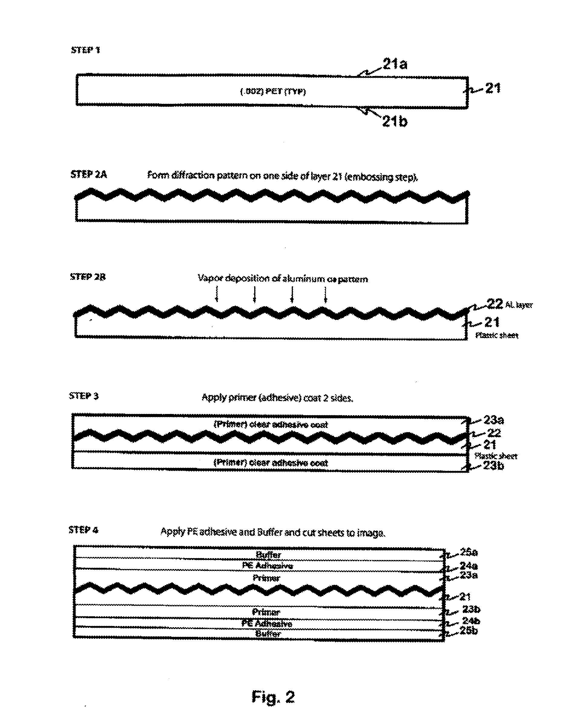
[0032]Referring to FIGS. 1, 2 and 2A, there is shown a core 20 comprised of a base layer 21 of a plastic material, which may be, for example, oriented polyester terephthalate (OPET) or polypropylene, or polystyrene, or any number of acrylics and / or a combination of these materials. The base layer 21 is shown to have an upper surface 21a and a lower, or bottom, surface 21b. For purpose of illustration, a pattern is shown to be formed on, or above, surface 21a of layer 21. However it should be understood that, alternatively, the pattern could be formed on surface 21b. Two different methods of forming a pattern are shown in FIGS. 2 and 2A. The surface 21a of layer 21 in FIG. 2 is embossed with a diffractive or holographic pattern. In FIG. 2A, the surface 21a of layer 21 is coated with an embossing layer 200 which is then embossed with a diffractive pattern, 200a.

[0033]A layer 22 of aluminum (or any suitable metal or metal compound such as Zinc Sulfide) may then be vapor deposited on t...


PUM

PropertyMeasurementUnit
thickaaaaaaaaaa
thickaaaaaaaaaa
thicknessaaaaaaaaaa

Abstract

Composite cards formed in accordance with the invention include a security layer comprising a hologram or diffraction grating formed at, or in, the center, or core layer, of the card. The hologram may be formed by embossing a designated area of the core layer with a diffraction pattern and depositing a thin layer of metal on the embossed layer. Additional layers may be selectively and symmetrically attached to the top and bottom surfaces of the core layer. A laser may be used to remove selected portions of the metal formed on the embossed layer, at selected stages of forming the card, to impart a selected pattern or information to the holographic region. The cards may be ‘lasered’ when the cards being processed are attached to, and part of, a large sheet of material, whereby the “lasering” of all the cards on the sheet can be done at the same time and relatively inexpensively. Alternatively, each card may be individually “lasered” to produce desired alpha numeric information, bar codes information or a graphic image, after the sheets are die-cut into cards.

Description

[0001]This application is a continuation application of my co-pending application Ser. No. 12 / 006,168 filed Dec. 31, 2007 and titled Foil Composite Card, the contents of which are incorporated herein by reference.BACKGROUND OF THE INVENTION[0002]The invention is directed to the manufacture of a multi-layered (composite) card, or any like instrument or document.[0003]The term “card” or “cards” as used herein, and in the appended claims, is intended to include a large variety of documents and instruments such as a financial cards, identification (including a National ID or Driver's License) cards, electronic passport pages, gift cards, documents for holding permanent and long lasting records such as medical records or security cards, or other plastic cards used for promotion of a product or organization.[0004]Various means of producing an improved composite card are disclosed in U.S. Pat. No. 6,644,552, titled Composite Card and issued to John Herslow, the applicant of this applicatio...

Claims


Application Information

Patent Timeline
Patent Type & Authority Applications(United States)
IPC IPC(8): G06K19/077H01L21/56
CPCB32B37/12B32B38/06B32B38/10B32B2038/0092B32B2310/0843B32B2367/00B32B2425/00B32B2429/00H01L2924/0002B42D25/41B42D25/328H01L2924/00G06K19/07749H01L21/561B42D25/425B42D25/435B32B7/12B32B15/04G06K19/06065G06K19/0775H01L23/4985H01L23/49855H01L23/57B42D25/373B42D25/47
Inventor HERSLOW, JOHN
Owner COMPOSECURE LLC
Why Eureka
Try Eureka