Encoder spectrograph for analyzing radiation using spatial modulation of radiation dispersed by wavelength

a spatial modulation and encoder technology, applied in the field of radiation spectrum analyzers and radiation image analyzers, can solve the problems of reducing the photometric accuracy of these instruments, reducing increasing the cost of encoders, etc., to achieve the effect of increasing the symmetry of the optics system, high compact encoder design, and small siz

Inactive Publication Date: 2007-08-28
MUDLOGGING SYST
View PDF45 Cites 7 Cited by
  • Summary
  • Abstract
  • Description
  • Claims
  • Application Information

AI Technical Summary

Benefits of technology

[0010]Embodiments of the invention provide many advantages over existing radiation analyzers. In some embodiments, an encoder spectrograph employs a double-crossover optics system that allows for a highly compact encoder design. The encoder spectrograph can be made even more compact by increasing the symmetry of the optics system, for example using optics having vertices in a common plane. The encoder spectrograph may have a dual optics system that allows for encoding of two radiation beams simultaneously, thus facilitating a number of useful applications. Various additional improvements enable an encoder spectrograph having a small size and increased performance relative to previous systems.
[0012]As described, in one embodiment, the path of the received beam crosses itself twice before reaching the detector. This double-crossover design allows the encoder spectrograph to be relatively small. In addition, the optics used to disperse, redirect, and collect or focus the beam at various stages in the optical path can be highly symmetric. The symmetry of the design further allows for a simpler and more compact encoder. Two or more of the optics components in the design may be mounted using a single mounting structure, thereby facilitating the manufacture of the encoder and the alignment of the optics in the device. In one embodiment, the diffraction grating is separately mounted, allowing for the removal of the grating and the installation of another grating, e.g., a grating designed for another application.
[0014]In another example, a single instrument employing two spectrographs is interfaced with two sampling sub-systems: an attenuated total reflectance (ATR) system for analyzing solids and / or liquids, and a gas cell for analyzing ambient air. In this manner, a first responder can analyze samples at the scene of an incident while simultaneously monitoring the ambient environment for potential hazards using a single instrument.
[0015]In another embodiment, to minimize phase error and maximize orthogonality, an in-situ phase analysis based on prime-number encoded components is used. The in-situ phases analysis may be performed using sine-only or cosine-only modulations to determine the phase of the encoded signals. In this way, the user can maximize the orthogonality of sine and cosine components having the same modulation frequency.
[0016]In another embodiment, the encoder spectrograph analyzes a continuous stream of spectra acquired during a calibration training mode. The spectrograph-encoder analyzer automatically logs those unique spectra required to build a calibration model, also called calibration training spectra. This enables a user to identify and quantify analytes by analyzing unknown spectra by acquiring the proper reference spectra required for the underlying calibration.
[0017]In another embodiment, a user can “tag” spectra with analyte species and concentration information, possibly during the collection of the calibration training spectra. One or more selected unique calibration training spectra can be compared with spectra from a spectral library or other database for further verification of assigned tags. In this way, users can share information and compare results between two or more instruments.

Problems solved by technology

While these analyzers offer superior spectral performance, they tend to be expensive, large, heavy and non-portable.
The processing of the additional, unnecessary optical data reduces the speed and compromises the photometric accuracy of these instruments.
As a consequence, the non-dispersive approach has clear limitations in adaptability and in the number of spectral components that can be analyzed.
Not only is this approach time consuming, it is prone to errors.
For example, as a direct consequence of the binary encoding approach, there is no mechanism by which one can recover the actual signal levels if any one of the signal levels changes significantly over the period of rotation.
However, this approach changes the optical duty cycle of each of the spectral components from its optimum value of 50%, thereby degrading the signal-to-noise ratio.
This significantly limits the instrument's adaptability.
None of the existing approaches is entirely satisfactory.

Method used


Image

  • Encoder spectrograph for analyzing radiation using spatial modulation of radiation dispersed by wavelength
  • Encoder spectrograph for analyzing radiation using spatial modulation of radiation dispersed by wavelength
  • Encoder spectrograph for analyzing radiation using spatial modulation of radiation dispersed by wavelength

Examples


Embodiment Construction

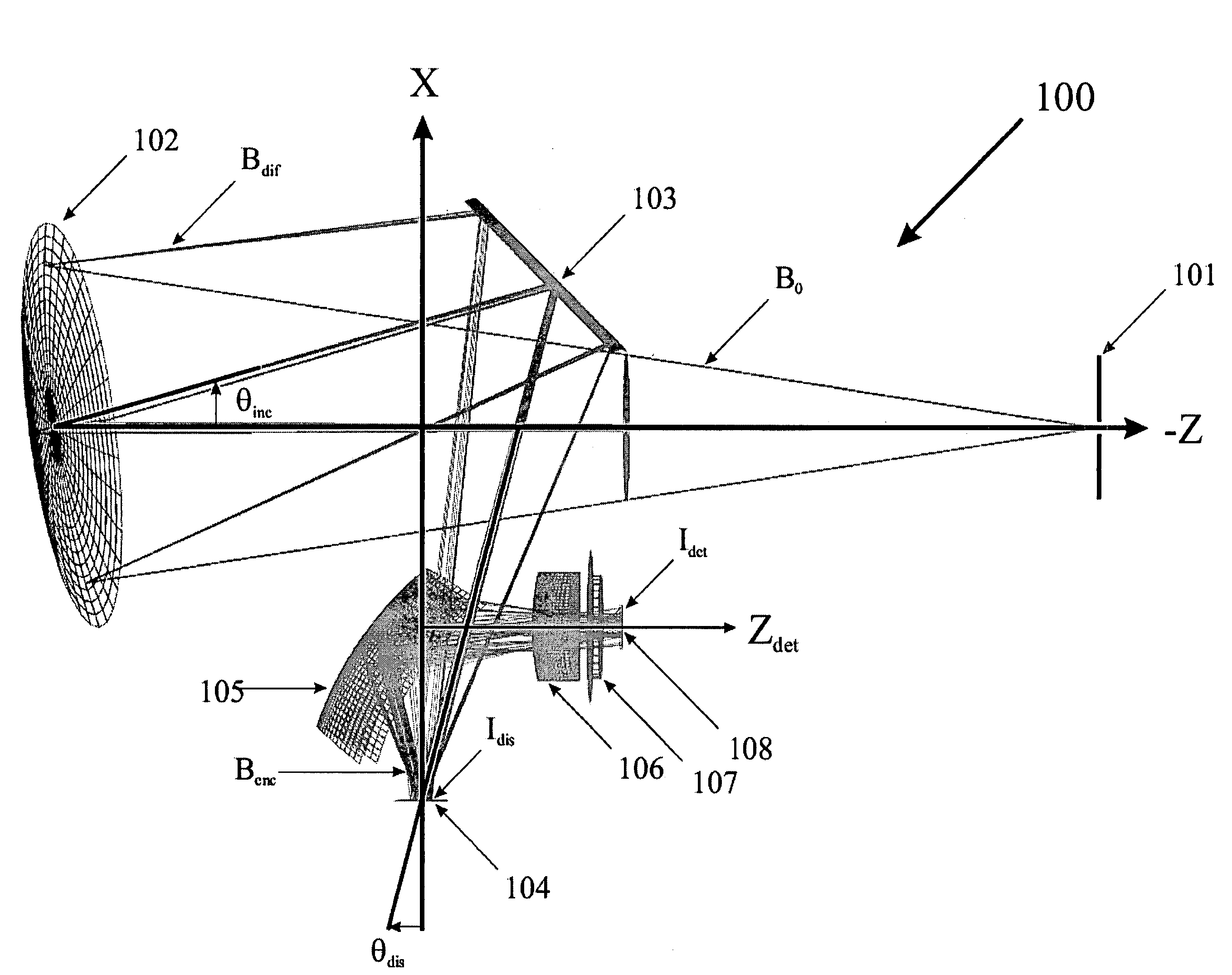
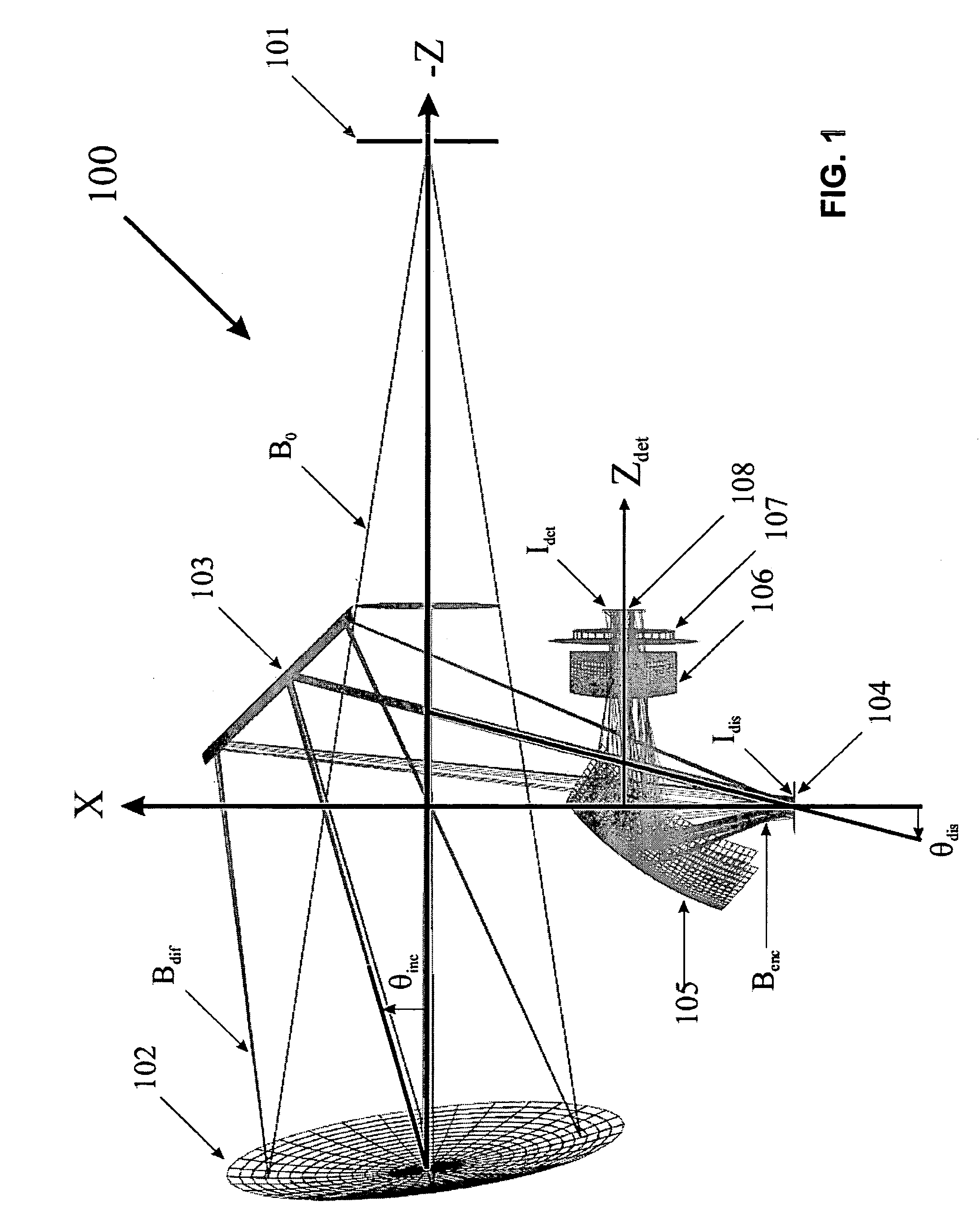
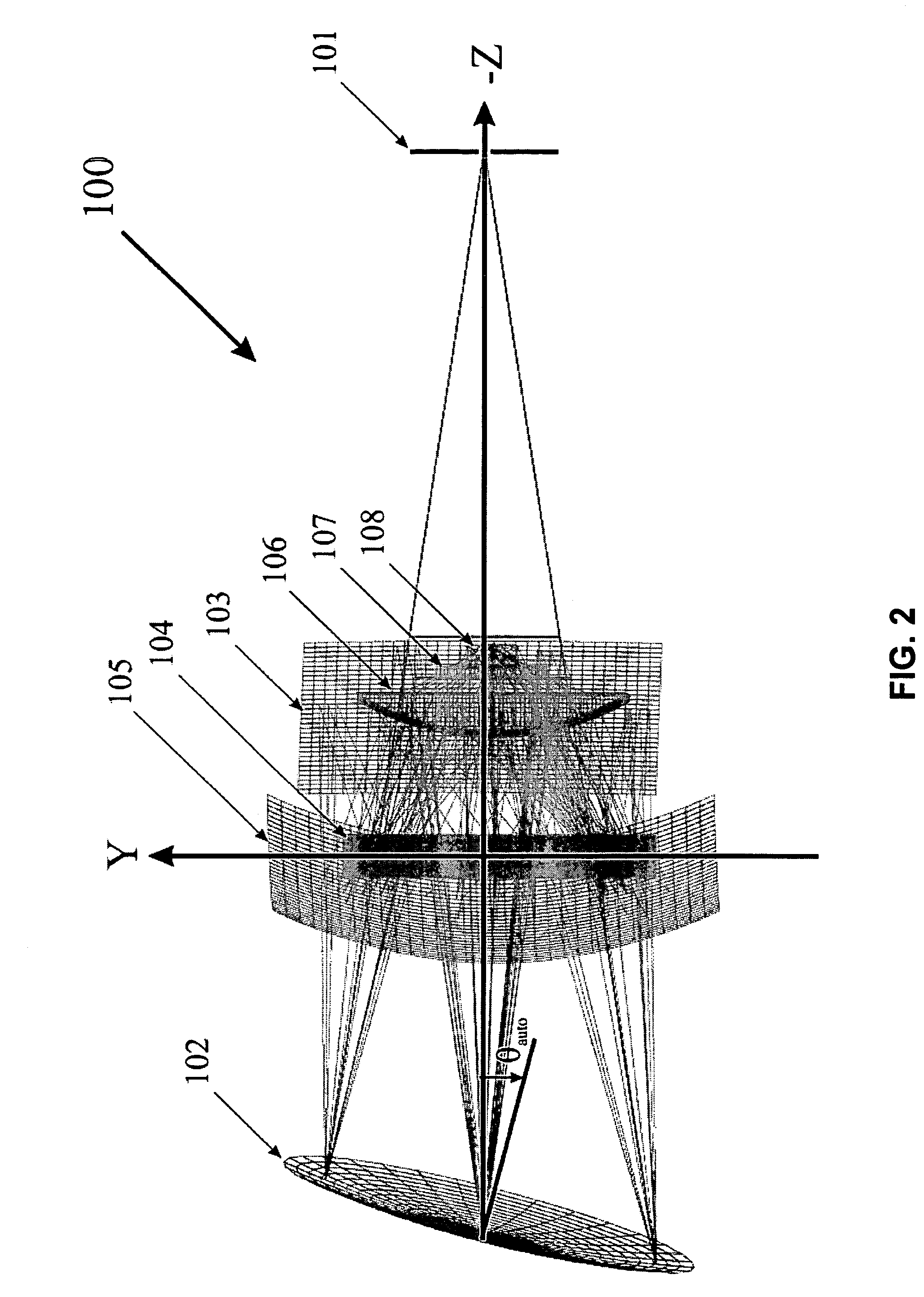
[0024]Disclosed herein are embodiments of an encoder spectrograph and related systems, subsystems, and applications for analyzing radiation from a sample. In various embodiments, an encoder spectrograph uses a spatial light modulator to encode dispersed radiation. The spatial light modulator for the encoder spectrograph may be implemented by a reflective modulator disc having a pattern of radiation intensity filters. Generally, embodiments of radiation analyzers and encoders that use spatial modulation of radiation dispersed by wavelength are described in U.S. Pat. No. 6,271,917, U.S. patent application Ser. No. 09 / 848,614, and U.S. patent application Ser. No. 10 / 384,374, each of which is incorporated by reference in its entirety. In one embodiment in accordance with the present invention, an encoder spectrograph comprises a Littrow-mount double-crossover optical system, which provides a number of advantages over previous designs.

Optical System for Encoder Spectrograph

[0025]FIG. 1 i...


PUM

PropertyMeasurementUnit
illuminated diameteraaaaaaaaaa
inclination angle θincaaaaaaaaaa

Abstract

An encoder spectrograph is used to analyze radiation from one or more samples in various configurations. The radiation is analyzed by spatially modulating the radiation after it has been dispersed by wavelength or imaged along a line. Dual encoder spectrographs may be used to encode radiation using a single modulator.

Description

CROSS REFERENCE TO RELATED APPLICATIONS[0001]This application claims the benefit of U.S. Provisional Application No. 60 / 583,834, filed Jun. 28, 2004, and U.S. Provisional Application No. 60 / 637,148, filed Dec. 16, 2004, each of which is incorporated by reference in its entirety.BACKGROUND[0002]1. Field of the Invention[0003]This invention relates in general to radiation spectrum analyzers and radiation image analyzers, and in particular, to radiation analyzers and encoders that use spatial modulation of radiation dispersed by wavelength.[0004]2. Background of the Invention[0005]Radiation spectral analysis is presently carried out in a number of ways. Dispersive and Fourier transform based analyzers are for high resolution and can be used for many different applications so that they are more versatile than existing application-specific instruments and procedures. While these analyzers offer superior spectral performance, they tend to be expensive, large, heavy and non-portable. For m...

Claims


Application Information

Patent Timeline
Patent Type & Authority Patents(United States)
IPC IPC(8): G01J3/28G01J3/18G01J3/42G01N21/31
CPCG01J3/02G01J3/0202G01J3/0208G01J3/0229G01J3/0291G01J3/0294G01J3/18G01J3/28G01J3/42G01N21/274G01N21/31G01N21/552G01N2021/317G01N2201/129
Inventor HAGLER, THOMAS W.
Owner MUDLOGGING SYST
Why Eureka
Try Eureka