Supercharge Your Innovation With Domain-Expert AI Agents!

Patridge sights and related methods

Active Publication Date: 2014-06-26
KENNEDY BRAD
View PDF0 Cites 3 Cited by
  • Summary
  • Abstract
  • Description
  • Claims
  • Application Information

AI Technical Summary

Benefits of technology

The patent describes a sighting system that can be used in different ways. It has a forward sight and a rear sight that can be opened to reveal a pointed rod. The system can be operated by aligning the post and notch and by aligning the post, block, and target. The system can also be operated by revealing the vertical point by hinging the post or by twisting it, or by opening the notched block to expose the horizontal point. These different modes allow for easier and more versatile use of the sighting system.

Problems solved by technology

However, Patridge sights and related variations thereof are not always satisfactory for use as weapon sights in circumstances that require accurate and speedy targeting of a long-range target.
Such sights are thought unsatisfactory in said circumstances because: (a) accurate vertical and horizontal alignment of said sights requires accurate estimation of horizontal and vertical alignment of the forward sight's post with the rear sight's notch plus accurate directional alignment of the weapon and target; and (b) because accurate and speedy mental estimation of those parameters requires a significant amount of training and practice.
Although generally speedy and accurate at long ranges, operation of lateral-point sighting systems is not always optimal.
For instance, lateral-point systems are not entirely satisfactory in circumstances requiring a clear view of a target because such systems involve the superimposition of a target point and target so that, as a result, such systems inherently obstruct the view of the sighted target.
For another instance, lateral point systems are sub-optimal in high-pressure situations (e.g., circumstances which require life-or-death targeting) because accurately touching tiny lateral points while superimposing a target point on a target is extremely difficult while under mental duress.
However, Patridge sights are not simply interchangeable with point-on-point sights given the differences in the configuration of forward sights (compare: forward lateral-points vs. a forward post), the configuration of rear sights (compare: rear lateral points vs. a rear notch through a block), and the mode of operation (compare: the touching of a forward point and a rear point plus superimposition of a target point and a target vs. the vertical, horizontal and directional alignment of a post, a notch, and a targe

Method used


Image

  • Patridge sights and related methods
  • Patridge sights and related methods
  • Patridge sights and related methods

Examples


Embodiment Construction

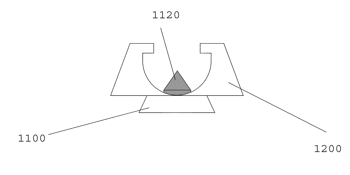
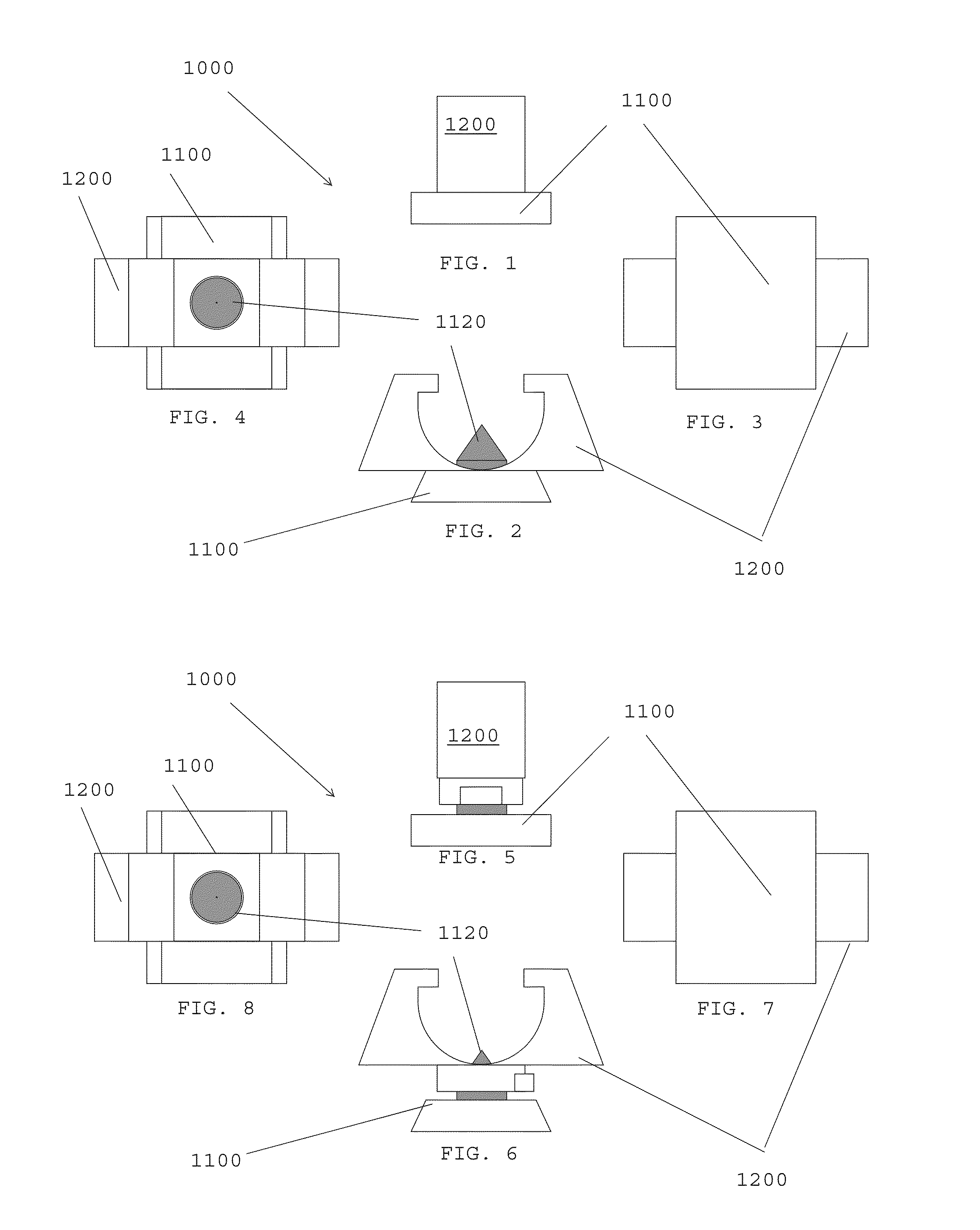
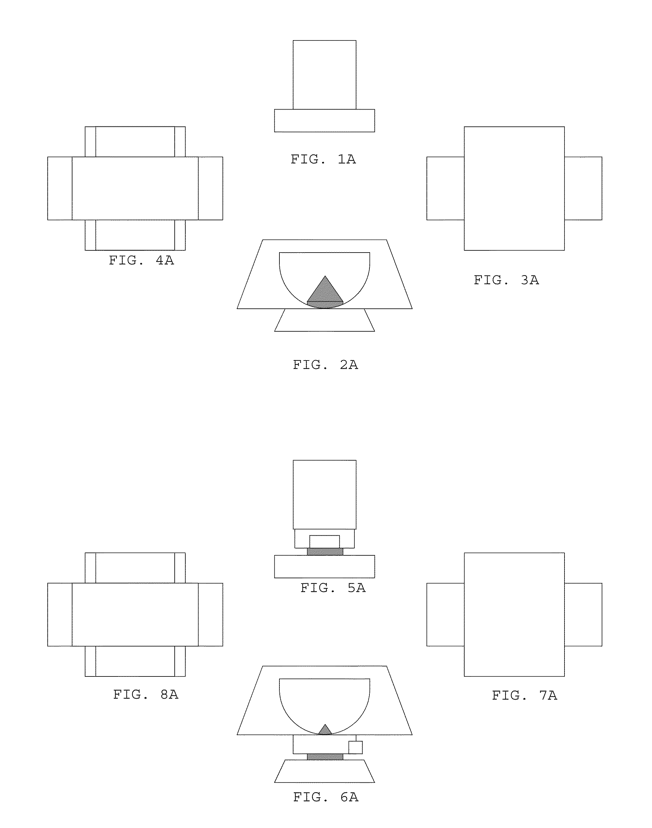
[0033]Disclosed are sighting systems that may be readily operable as both point-on-point and Patridge sighting systems. Generally, the disclosed sighting system is a Patridge sighting system that is convertible or transformable into a point-on-point sighting system and vice-versa. The system features: a forward sight at the front of a weapon, wherein said forward sight is defined by a post with a concealed and vertically oriented pointed rod; a rear sight at the back of the weapon, wherein the rear sight is defined by a notched block with a concealed and horizontally oriented pointed rod. In an alternate embodiment, the forward sight has a horizontally oriented pointed rod instead of a vertical oriented pointed rod and the rear sight has a vertically oriented pointed rod instead of a horizontally oriented pointed rod. The more specific aspects of the system are best disclosed with reference to the attached drawings.

[0034]FIGS. 1 through 8 depict a preferable embodiment of a forward ...


PUM


Abstract

Disclosed is an improved open sight that may be operated as a Patridge sight and point-on-point sight.

Description

CROSS-REFERENCE TO RELATED APPLICATIONS[0001]Not Applicable.STATEMENT REGARDING FEDERALLY SPONSORED RESEARCH OR DEVELOPMENT[0002]Not applicable.BACKGROUND OF THE INVENTION[0003]1. Field of Invention[0004]This application is in the field of improved open-sights and related methods.[0005]2. Background of the Invention[0006]Generally, open-sights are alignment markers used for aiming firearms or other projectile based weapons (collectively “weapons”). Open sights are comprised of a forward sight and a rear sight which provide horizontal and vertical references so that the same may be aligned to ensure that a weapon is properly trained toward a target. For firearms, the forward sight may be a post at the front end of a barrel and the rear sight is typically a notch or peephole at the rear end of the barrel. In many instances, open-sights are operated via aligning the forward and rear sights along a line of sight of a user.[0007]The most common species within the genus of open sights are...

Claims


Application Information

Patent Timeline
IPC IPC(8): F41G1/16
CPCF41G1/16F41G1/01F41G1/17F41G1/033F41G1/02F41G1/20F41G1/42
Inventor KENNEDY, BRAD
Owner KENNEDY BRAD
Features
  • R&D
  • Intellectual Property
  • Life Sciences
  • Materials
  • Tech Scout
  • Unparalleled Data Quality
  • Higher Quality Content
  • 60% Fewer Hallucinations
Learn More