Accessory Drive With Friction Clutch And Electric Motor

Inactive Publication Date: 2014-06-26
BORG WARNER INC
View PDF6 Cites 16 Cited by
  • Summary
  • Abstract
  • Description
  • Claims
  • Application Information

AI Technical Summary

Benefits of technology

[0007]When the solenoid is on, the solenoid force overcomes the force of the biasing members and causes the plate to contact the pulley, and another spring or biasing member spaces the plate away from the cover and holds i

Problems solved by technology

In one embodiment, when the solenoid is off for any reason,

Method used


Image

  • Accessory Drive With Friction Clutch And Electric Motor
  • Accessory Drive With Friction Clutch And Electric Motor
  • Accessory Drive With Friction Clutch And Electric Motor

Examples


Embodiment Construction

[0016]For the purpose of promoting and understanding the principles of the present invention, reference will now be made to the embodiments illustrated in the drawings and specific language will be used to describe them. It will nevertheless be understood that no limitation as to the scope of the invention is hereby intended. The invention includes any alternatives and other modifications in the illustrated devices and described methods and further applications of the principles of the invention which would normally occur to persons or ordinary skill in the art to which the invention relates.

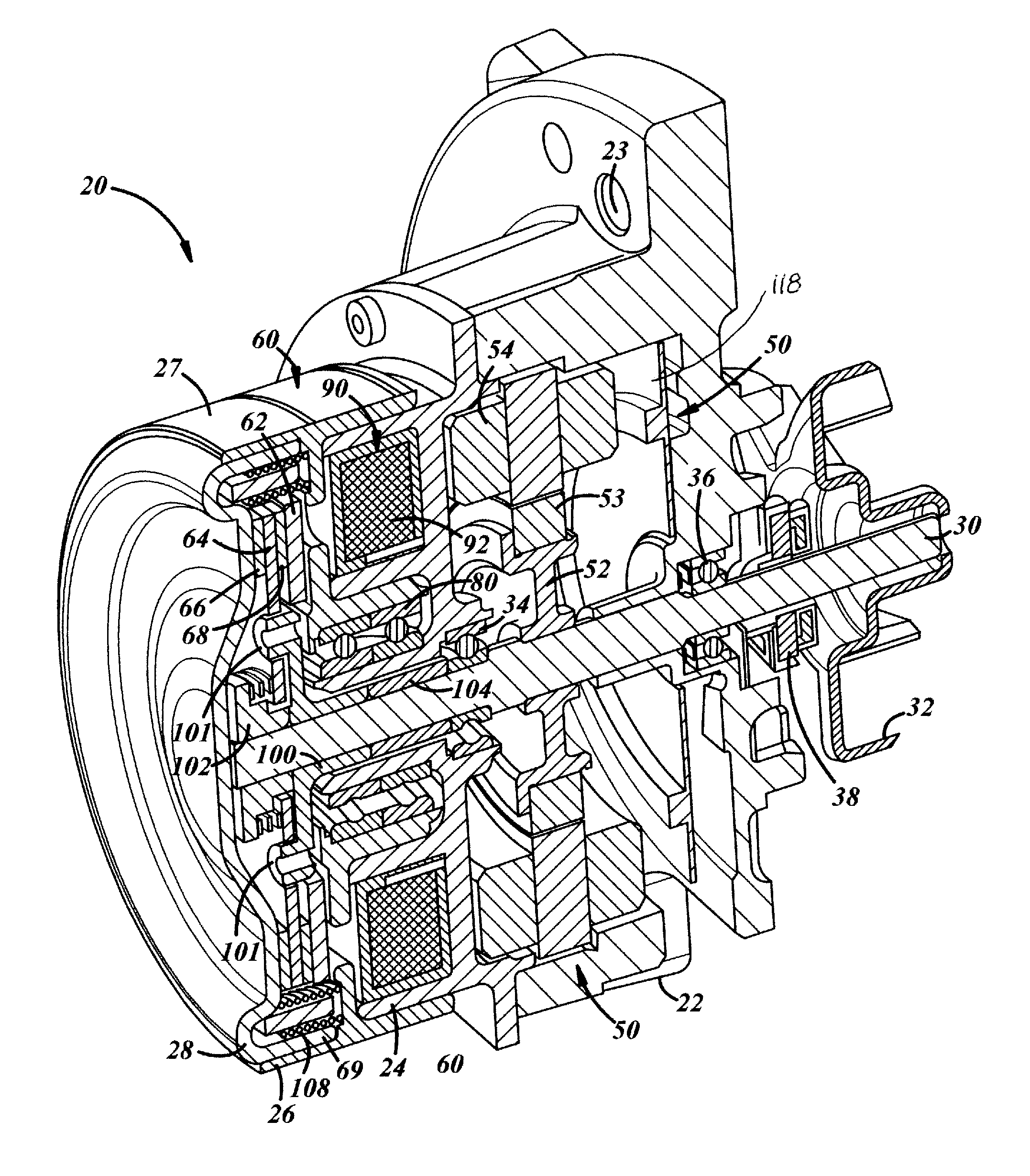
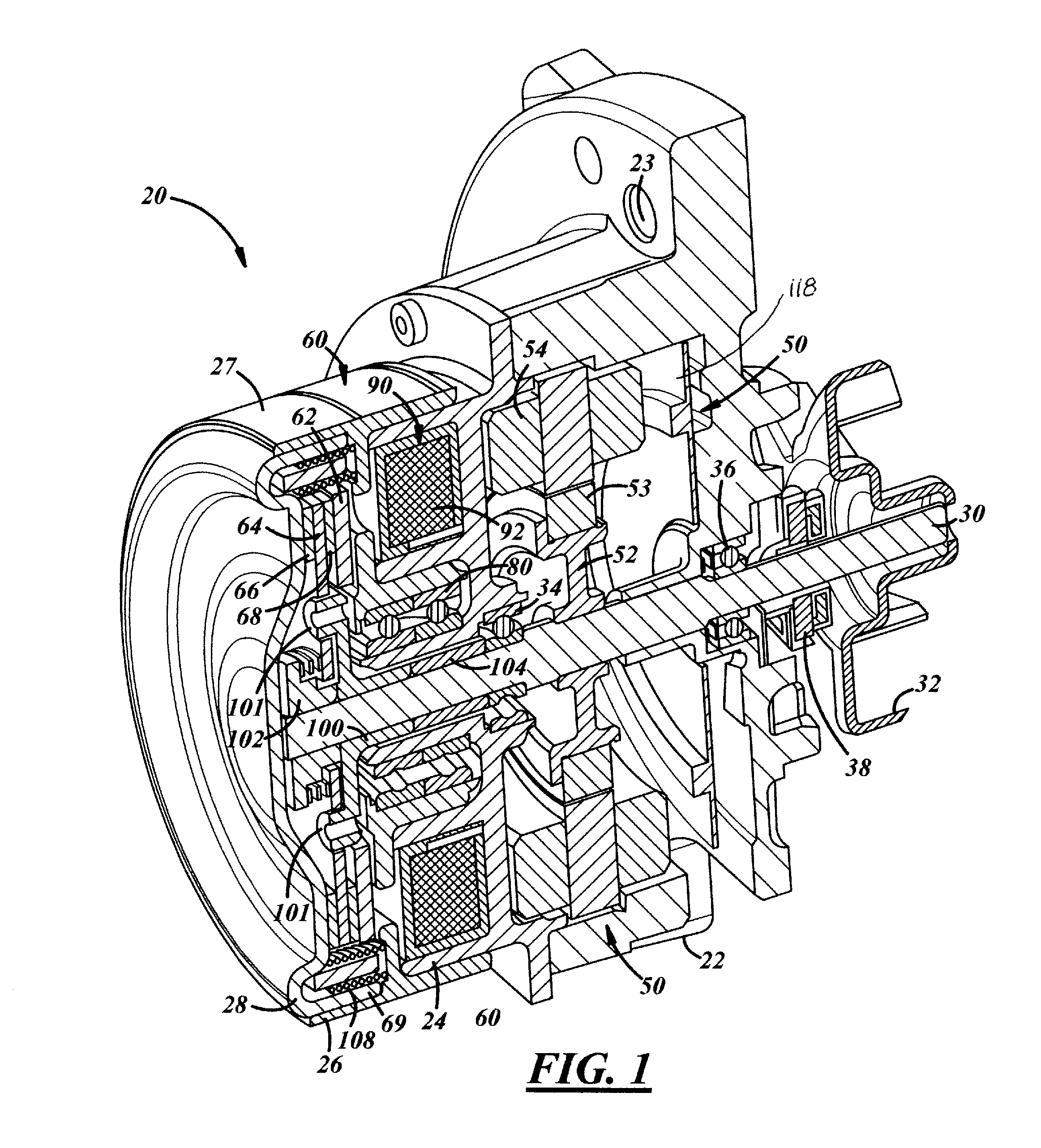
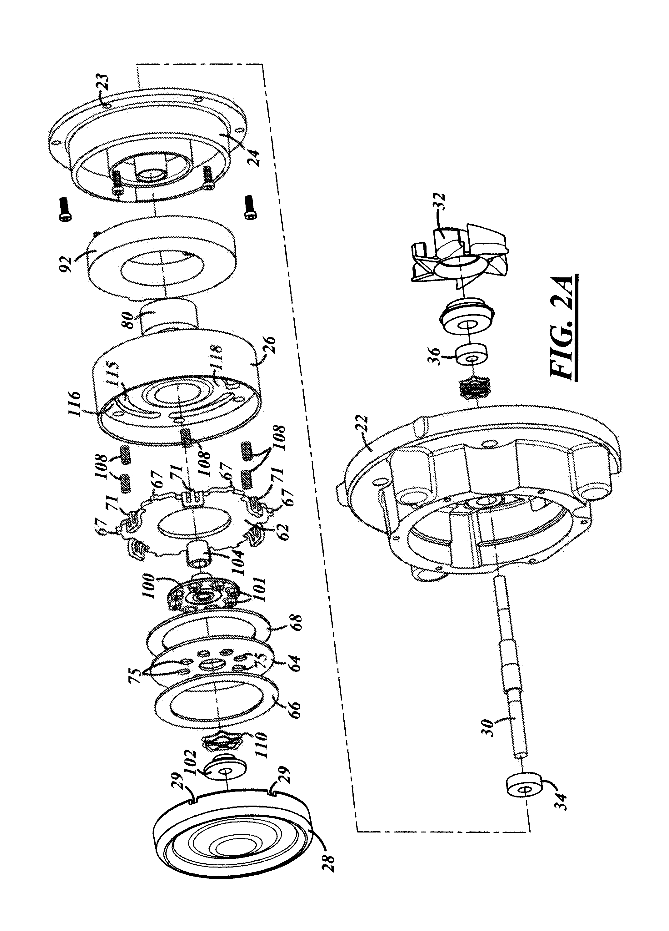
[0017]The present inventions described herein relate to dual mode friction clutch assemblies particularly used for accessories, such as coolant pumps and fans which circulate coolant or air into or through an engine, such as an automobile internal combustion engine. (The terms “water pump” and “coolant pump” are used interchangeably herein.) The present invention, however, can also be used for o...


PUM


Abstract

A friction clutch assembly for a vehicle accessory, particularly to drive a vehicle cooling pump, and more particularly as part of a dual mode drive for a cooling pump, together with an electric motor. The friction clutch assembly includes a friction plate member connected to a central rotatable shaft member used for operating the vehicle accessory. A biased armature member is adapted to force a friction plate member with friction linings thereon against a housing or cover which is rotating at input speed. A solenoid assembly is used to overcome the spring bias and pull the armature and friction plate member away from the housing.

Description

CROSS-REFERENCE TO RELATED APPLICATIONS[0001]This application is a continuation-in-part of U.S. patent application Ser. No. 14 / 135,280 (DKT12180A (BWA 0427 PUS) filed on Dec. 19, 2013, which is a non-provisional of U.S. Patent Application No. 61 / 745,647, filed on Dec. 24, 2012. This application is also related to U.S. Patent Application Ser. No. 61 / 474,862 and U.S. Patent Application Ser. No. 61 / 474,928, both filed on Apr. 13, 2011.TECHNICAL FIELD[0002]Improved friction clutch assemblies, particularly for hybrid accessory drives for coolant pumps and the like.BACKGROUND[0003]Vehicle engine accessories, such as water pumps and cooling fans, are in common use in automobiles and other vehicles. These accessories are typically driven by a belt attached to the crankshaft of the engine and thus operate at some percentage of engine speed. The water pumps have an impeller that is used to circulate the engine coolant from the engine to the radiator and back in order to keep the coolant withi...

Claims


Application Information

Patent Timeline
IPC IPC(8): F16D27/112
CPCF16D13/76F16D48/064F16D2500/1045F16D2500/5106F16D2500/5114F16D27/112F04D13/021F04D13/06
Inventor QIN, SHIWEI
Owner BORG WARNER INC
Why Eureka
Try Eureka