IR sensor with increased surface area

a technology of infrared sensors and surface area, applied in the field of infrared sensors, can solve the problem of inherently long reaction time of infrared radiation detectors

Active Publication Date: 2014-07-03
ILLINOIS TOOL WORKS INC
View PDF49 Cites 3 Cited by
  • Summary
  • Abstract
  • Description
  • Claims
  • Application Information

AI Technical Summary

Problems solved by technology

These infrared radiation detectors are satisfactory for some purposes, but the reaction time in such infrared radiation detectors is inherently long since the operation depends entirely upon a therma...

Method used


Image

  • IR sensor with increased surface area
  • IR sensor with increased surface area
  • IR sensor with increased surface area

Examples


Embodiment Construction

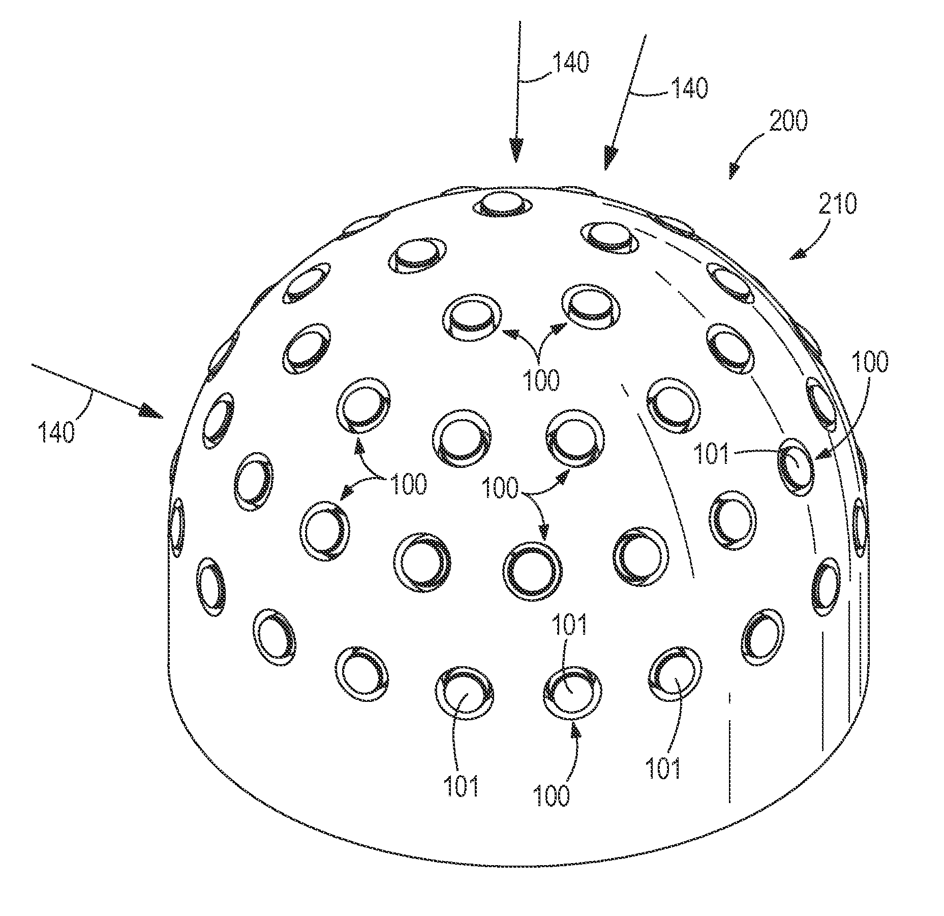
[0021]Sometimes, infrared radiation detectors may be arranged in a spherical or semispherical array in order to detect infrared radiation such as, for example, from gunfire. Currently, infrared radiation detectors often use square or rectangular sensor elements 250, shown in FIG. 4 laid over a sensor element 101 of the present disclosure for comparative purposes, to detect infrared radiation housed in a round, can housing. The issue with such a configuration is that since the sensor elements are square and the housing is round, there is a substantial amount of area in which no detection can occur, called dead spots. If infrared radiation falls on a dead spot, little or no detection can occur. As a result, it would be desirable to reduce the amount of dead spots in an array in order to increase the chance of detecting emitted infrared radiation from, for example, a gunshot.

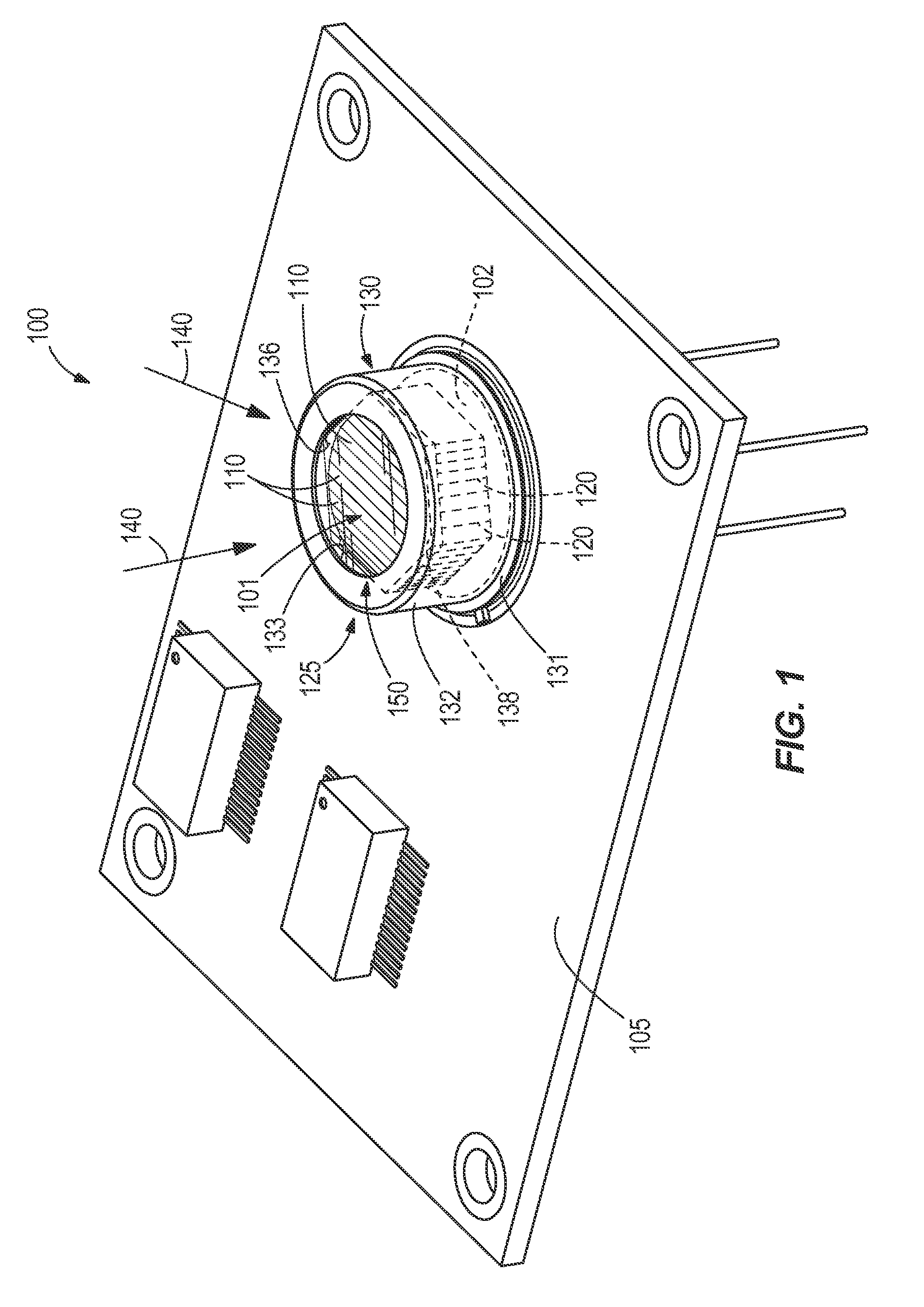
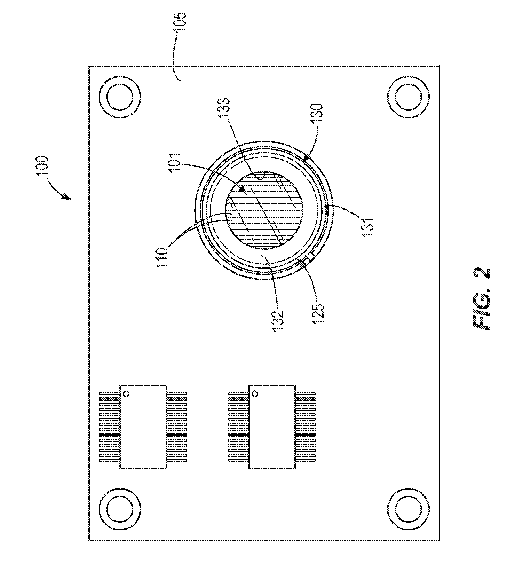
[0022]The present disclosure makes use of the discovery that by disposing a sensor element with more than four s...


PUM


Abstract

Sensors, systems including sensors, and methods of using such sensors and systems are provided. In one aspect, a sensor includes a sensor element at least partially positioned within the housing. The sensor element includes a plurality of interconnected segments with each segment comprising a pyroelectric crystal and wherein the sensor may generate a single, unitary signal upon exposure of any segment to infrared radiation.

Description

RELATED APPLICATIONS[0001]The present application claims the benefit of co-pending U.S. Provisional Patent Application No. 61 / 747,037, filed Dec. 28, 2012, the entire contents of which is incorporated herein by reference.FIELD OF THE INVENTION[0002]The present disclosure generally relates to infrared sensors and, more particularly, to infrared sensors with increased surface area.BACKGROUND[0003]An infrared (IR) radiation detector responds to thermal energy such as, for example, infrared radiation radiated by objects such as, for example, animals, automobiles, airplanes, gunfire, missiles, explosions, fire, etc. This thermal energy is typically not visible to the human eye. Accordingly, by using an infrared radiation detector, objects that are not visible may be perceived and / or alternative views of visible objects may be obtained.[0004]Materials are known that may be excited by the absorption of infrared energy to provide a useful electrical signal for an infrared radiation detector...

Claims


Application Information

Patent Timeline
IPC IPC(8): G01J5/34
CPCG01J5/34G01J1/0266G01J5/045G01J5/0871
Inventor SMITH, THOMAS W.
Owner ILLINOIS TOOL WORKS INC
Why Eureka
Try Eureka