Magnetron and device using microwaves related applications

a technology of microwaves and antenna caps, applied in the field of magnets, can solve the problems of difficult to maintain the adhesive strength between the antenna cap and the exhaust pipe, and the document 1 and 2 cannot fully suppress so as to achieve the effect of reliably suppressing the removal of the antenna cap

Inactive Publication Date: 2014-07-10
PANASONIC INTELLECTUAL PROPERTY MANAGEMENT CO LTD
View PDF7 Cites 4 Cited by
  • Summary
  • Abstract
  • Description
  • Claims
  • Application Information

AI Technical Summary

Benefits of technology

[0023]The magnetron according to the present invention can further reliably suppress the removal of the antenna cap, since the antenna cap and the exhaust pipe are welded to each other.

Problems solved by technology

In this case, since a press fit length of the antenna cap and the exhaust pipe becomes short, the structures of Patent documents 1 and 2 cannot fully suppress removal of the antenna cap.
However, in this structure, under a condition of heat cycle caused by repeating switching ON / OFF of the magnetron, it is difficult to continuously maintain the adhesive strength between the antenna cap and the exhaust pipe.

Method used


Image

  • Magnetron and device using microwaves related applications
  • Magnetron and device using microwaves related applications
  • Magnetron and device using microwaves related applications

Examples


embodiment

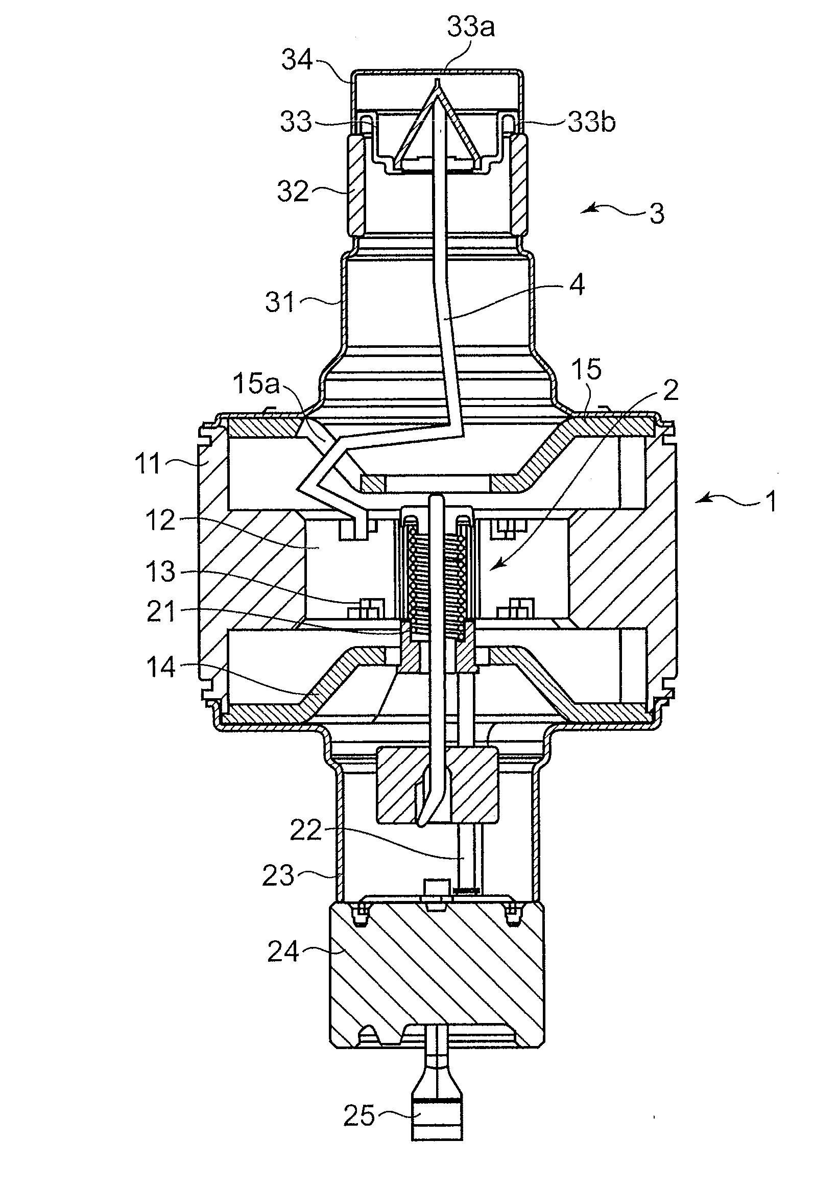
[0039]A description will be given of a magnetron according to an embodiment of the present invention. The magnetron according to the present embodiment is used in a device using microwaves, such as a microwave oven and a thermotherapy device. FIG. 1 is a longitudinal sectional view showing an overall structure of the magnetron according to the present embodiment.

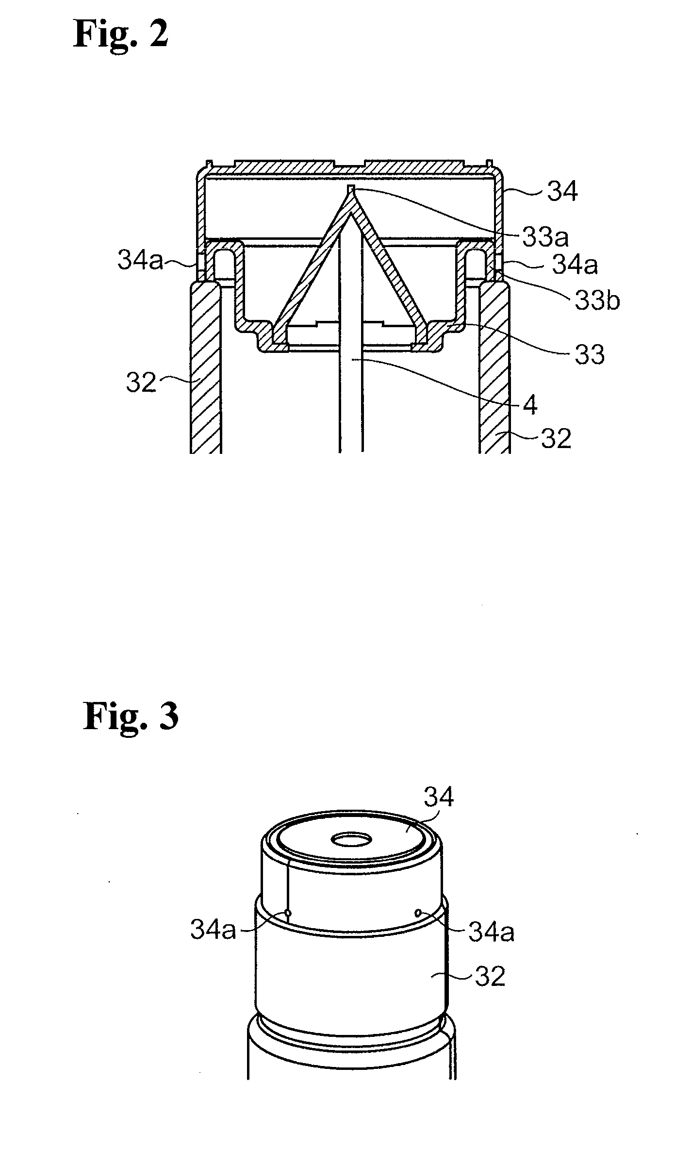
[0040]As shown in FIG. 1, the magnetron according to the present embodiment is provided with an anode portion 1, a cathode portion 2, an output portion 3, and an output antenna 4.

[0041]The anode portion 1 has a cylindrical anode cylinder 11, and a plurality of vanes 12 radially arranged inside the anode cylinder 11. The plurality of vanes 12 is electrically connected in an alternate manner to every other strap rings 13 having different diameters. In addition, an input side opening and an output side opening of the anode cylinder 11 are provided with pole pieces 14 and 15, respectively, for concentrating a magnetic field on a...


PUM


Abstract

The magnetron according to the present invention includes an anode portion, a cathode portion arranged in a central portion of the anode portion, an output antenna connected to the anode portion, an exhaust pipe arranged around the output antenna to serve as a part of a vacuum tube, and an antenna cap covering a chip-off portion included in the exhaust pipe. The antenna cap and the exhaust pipe are welded to each other.

Description

BACKGROUND OF THE INVENTION[0001]1. Field of the Invention[0002]The present invention relates to a magnetron used in a device using microwaves, such as a microwave oven and a thermotherapy device, and more particularly to a structure of a connecting portion of an exhaust pipe and an antenna cap.[0003]2. Description of the Related Art[0004]Conventionally, as a magnetron of this type, there has been known, for example, a structure shown in FIG. 4.[0005]In FIG. 4, a conventional magnetron is provided with an anode portion 101, a cathode portion 102, an output portion 103, and an output antenna 104.[0006]The anode portion 101 has a cylindrical anode cylinder 111, and a plurality of vanes 112 radially arranged inside the anode cylinder 111. The plurality of vanes 112 is electrically connected in an alternate manner to every other strap rings 113 having different diameters. In addition, an input side opening and an output side opening of the anode cylinder 111 are provided with pole piece...

Claims


Application Information

Patent Timeline
Patent Type & Authority Applications(United States)
IPC IPC(8): H01J23/12H01J25/50
CPCH01J25/50H01J23/12H01J25/587
Inventor ISHII
Owner PANASONIC INTELLECTUAL PROPERTY MANAGEMENT CO LTD
Why Eureka
Try Eureka