Header

a header and head technology, applied in the field of headers, can solve the problems of increasing the wear on the conveyor belt, the difficulty of belt guidance and belt sealing, etc., and achieve the effects of reducing gap formation, improving salability, and improving sealability

Active Publication Date: 2014-07-17
CLAAS SELBSTFAHRENDE ERNTEMASCHINEN GMBH
View PDF20 Cites 29 Cited by
  • Summary
  • Abstract
  • Description
  • Claims
  • Application Information

AI Technical Summary

Benefits of technology

[0009]Each side section also comprises a plurality of supporting elements. The supporting elements support the conveyor belt and are supported in a bearing point such that these supporting elements are displaceable in the axial direction relative to the main frame. The displaceability of the supporting elements in response to a vertical deflection of the finger bar makes tracking by the conveyor belt possible according to the course of motion occurring upon deflection of the finger bar. Hence, the conveyer belt so designed is largely prevented from tightening between mutually adjacent supporting elements, thereby resulting in improved sealability. The improved salability reduces wear on the conveyor belt.
[0010]Preferably, the bearing point of the particular supporting element is designed as a sliding joint. The gliding joint permits translatory motion as well rotational motion about the longitudinal axis of the supporting arm makes it possible for the front conveyor belt section (which faces the finger bar) to better adapt to the wave-shaped motion occurring upon deflection of the finger bar. The gap formation is markedly reduced as a result.

Problems solved by technology

The belt guidance and the belt sealing are made difficult as a result.
In addition, the conveyor belt is exposed, at some points, to greater loads due to friction and deformation, thereby increasing the wear on the conveyor belt.

Method used


Image

  • Header
  • Header
  • Header

Examples


Embodiment Construction

[0030]The following is a detailed description of example embodiments of the invention depicted in the accompanying drawings. The example embodiments are presented in such detail as to clearly communicate the invention and are designed to make such embodiments obvious to a person of ordinary skill in the art. However, the amount of detail offered is not intended to limit the anticipated variations of embodiments; on the contrary, the intention is to cover all modifications, and alternatives falling within the spirit and scope of the present invention, as defined by the appended claims.

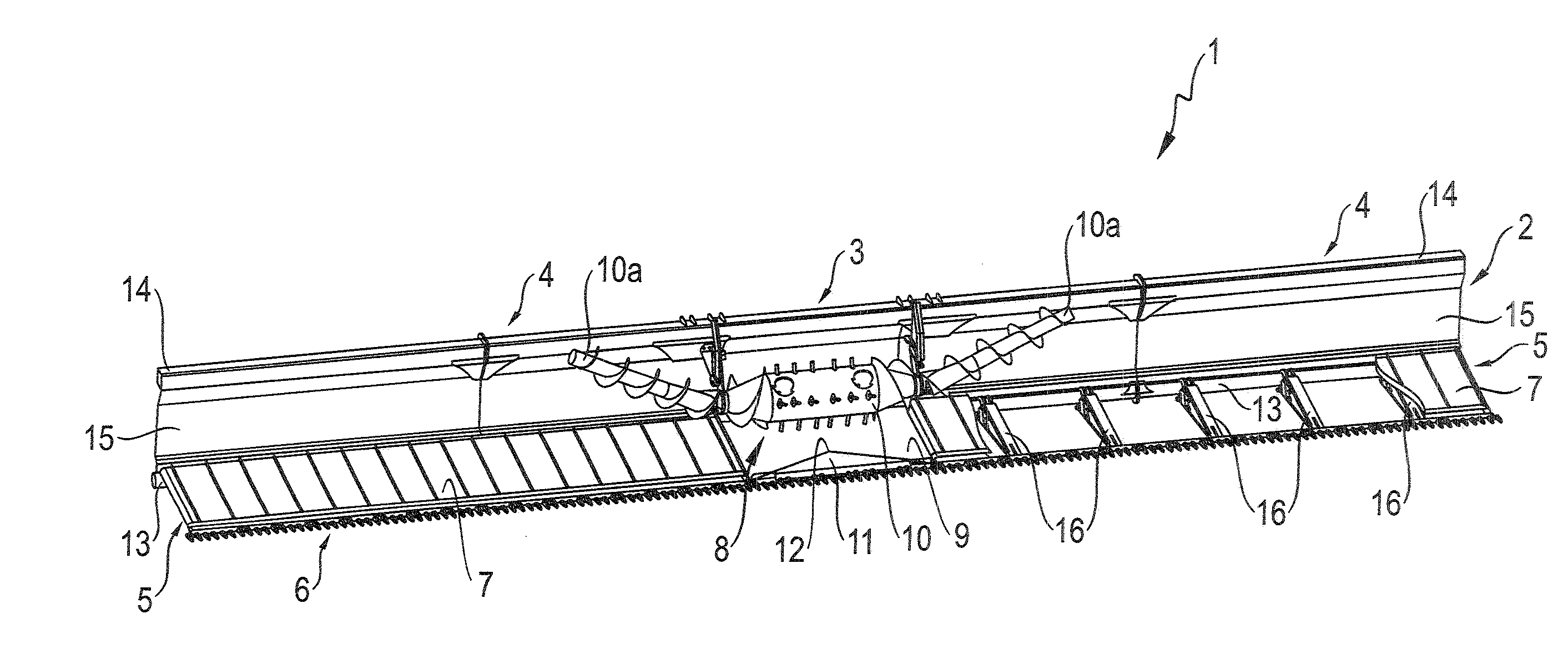
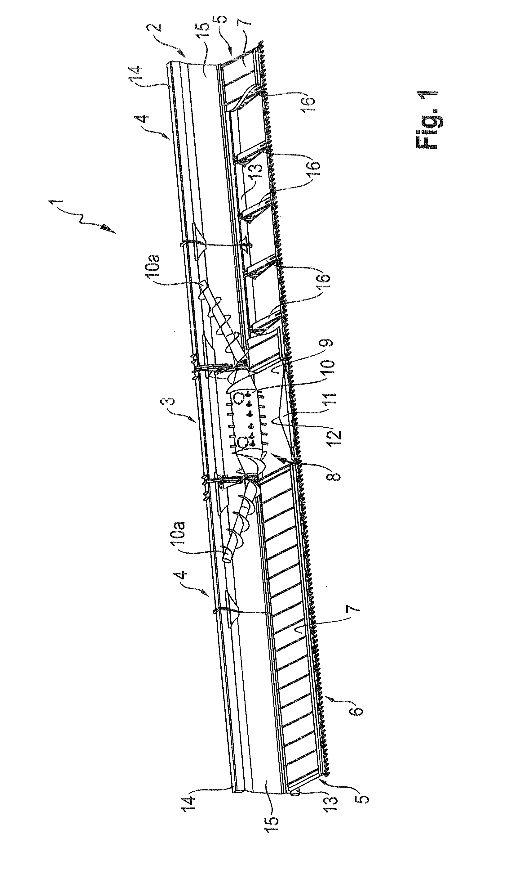
[0031]As mentioned above, FIG. 1 depicts a schematic, partially exposed view of a header 1 according to the invention. The header 1 comprises a main frame 2, on which a middle section 3 and at least two side sections 4 adjacent to the middle section 3 are disposed. A continuous, flexible finger bar 6 extends substantially across the entire width of the header 1, including the middle section 3 and the si...


PUM


Abstract

A header has a middle section disposed on a main frame, at least two side sections adjacent to the middle section, a rear panel extending perpendicularly to the main frame, a flexible finger bar extending across a width of the header and a conveyor device disposed behind the finger bar. The conveyer device is designed on the side sections as a continuous conveyor belt disposed adjacent to the middle section in order to transport crop cut by the finger bar laterally in the direction of the middle section. The side sections are formed as a plurality of supporting arms swivellably disposed on the main frame that support the finger bar. Each side section has a plurality of supporting elements for supporting the conveyor belt. Each of the supporting elements is supported in a bearing point to be displaceable in the axial direction relative to the main frame.

Description

CROSS-REFERENCE TO A RELATED APPLICATION[0001]The invention described and claimed hereinbelow is also described in German Priority Document DE 10 2013 100322.2, filed on Jan. 14, 2013. The German Priority Document, the subject matter of which is incorporated herein by reference, provides the basis for a claim of priority of invention under 35 U.S.C. 119(a)-(d).BACKGROUND OF THE INVENTION[0002]The invention relates broadly to a header with a middle section disposed on a main frame and at least two side sections disposed adjacent to the middle section, a rear panel extending substantially perpendicularly to the main frame, a flexible finger bar extending across the width of the header and at least one conveyor device disposed behind the finger bar, where the at least one conveyor device is designed, on the respective side sections, as at least one continuous conveyor belt and where the conveyor belt(s) is / are disposed adjacent to the middle section in order to transport crop cut by th...

Claims


Application Information

Patent Timeline
Patent Type & Authority Applications(United States)
IPC IPC(8): A01D43/06
CPCA01D43/06A01D41/14A01D61/002A01D34/00
Inventor FUECHTLING, CHRISTIAN
Owner CLAAS SELBSTFAHRENDE ERNTEMASCHINEN GMBH
Why Eureka
Try Eureka