End effector module

Inactive Publication Date: 2014-07-17
PRECISION MACHINERY RES & DEV CENT
View PDF4 Cites 66 Cited by
  • Summary
  • Abstract
  • Description
  • Claims
  • Application Information

AI Technical Summary

Benefits of technology

[0006]In view of the aforementioned problems, it is a primary objective of the present invention to provide an end effector module that drives a gear by a motor installed at each joint shaft in order to drive a whole robotic finger to rotate while driving another gear to dri

Problems solved by technology

In other words, the motion of the robotic finger has only one degree of freedom and fails to make a fine angular adjustment of the joint shaft, and it is relatively difficult to move

Method used


Image

  • End effector module
  • End effector module
  • End effector module

Examples


Embodiment Construction

[0015]The technical characteristics of the present invention will become apparent with the detailed description of the preferred embodiments accompanied with the illustration of related drawings as follows.

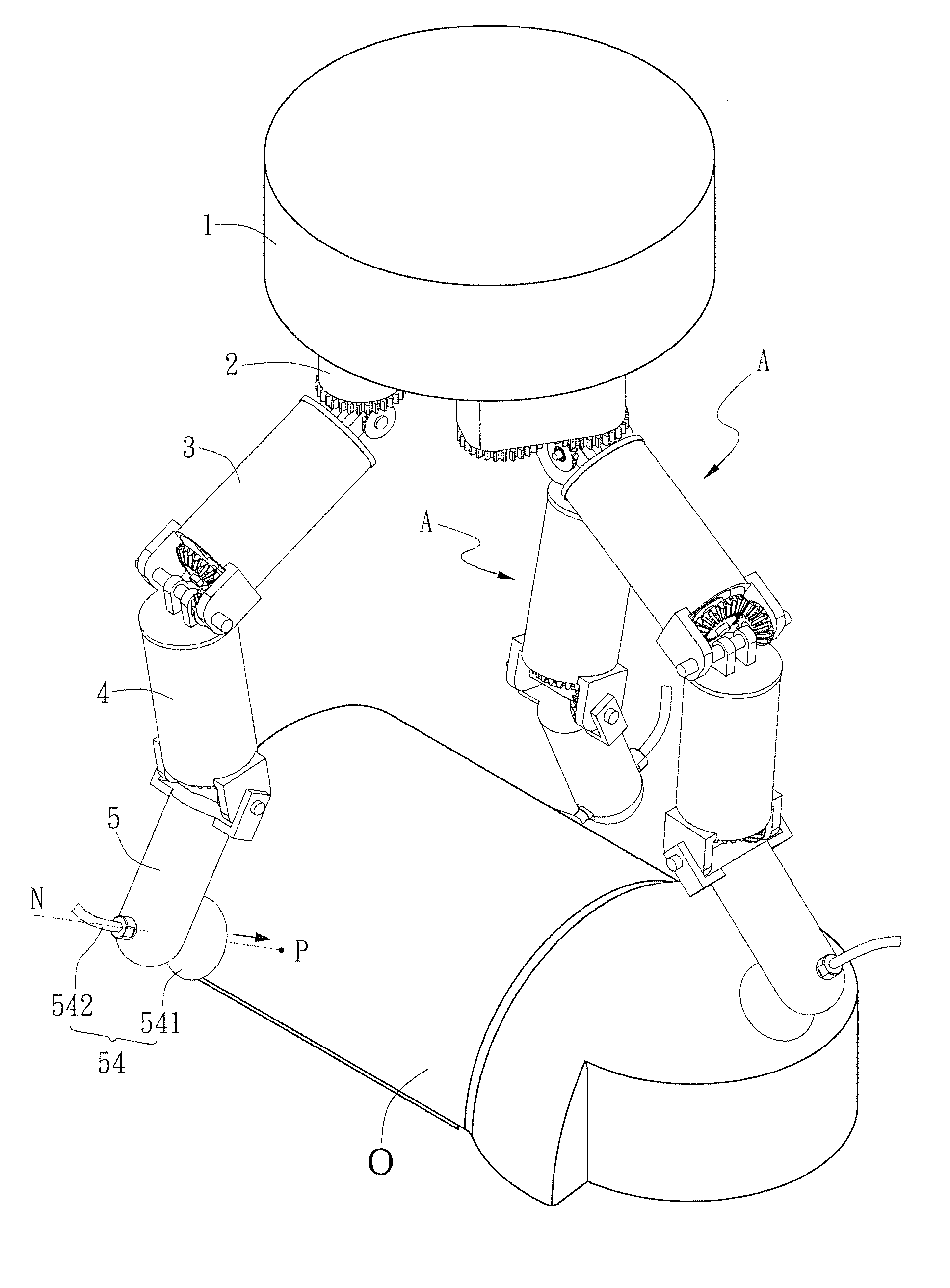
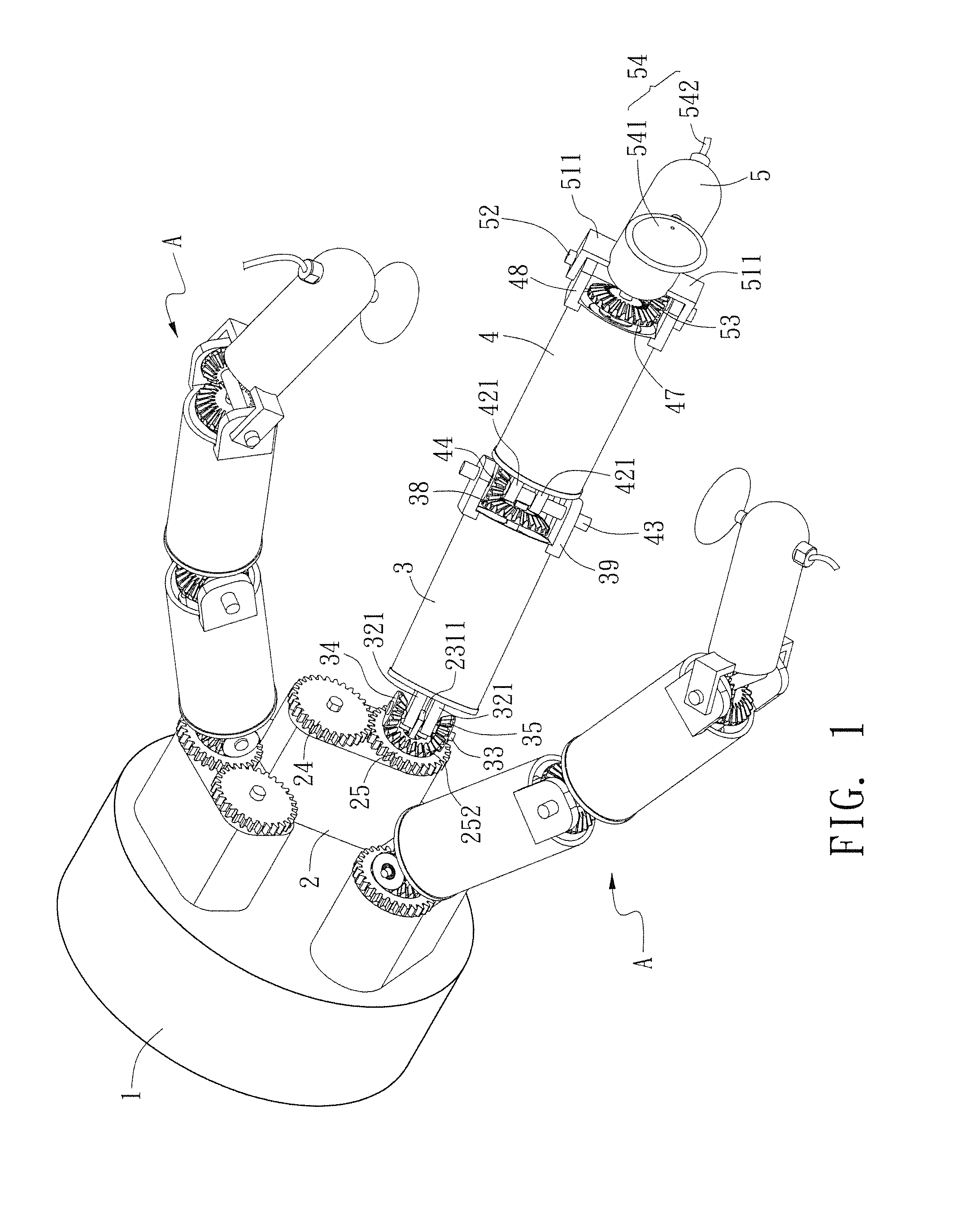
[0016]With reference to FIGS. 1 and 2 for an end effector module of the present invention, the end effector module comprises a palm base 1, and a plurality of robotic fingers A extended from a same side of the palm base 1, wherein each robotic finger A is formed by sequentially and pivotally coupling a start joint shaft 2, a first middle joint shaft 3, a second middle joint shaft 4 and an end joint shaft 5, and the structure of each of the joint shafts is described as follows.

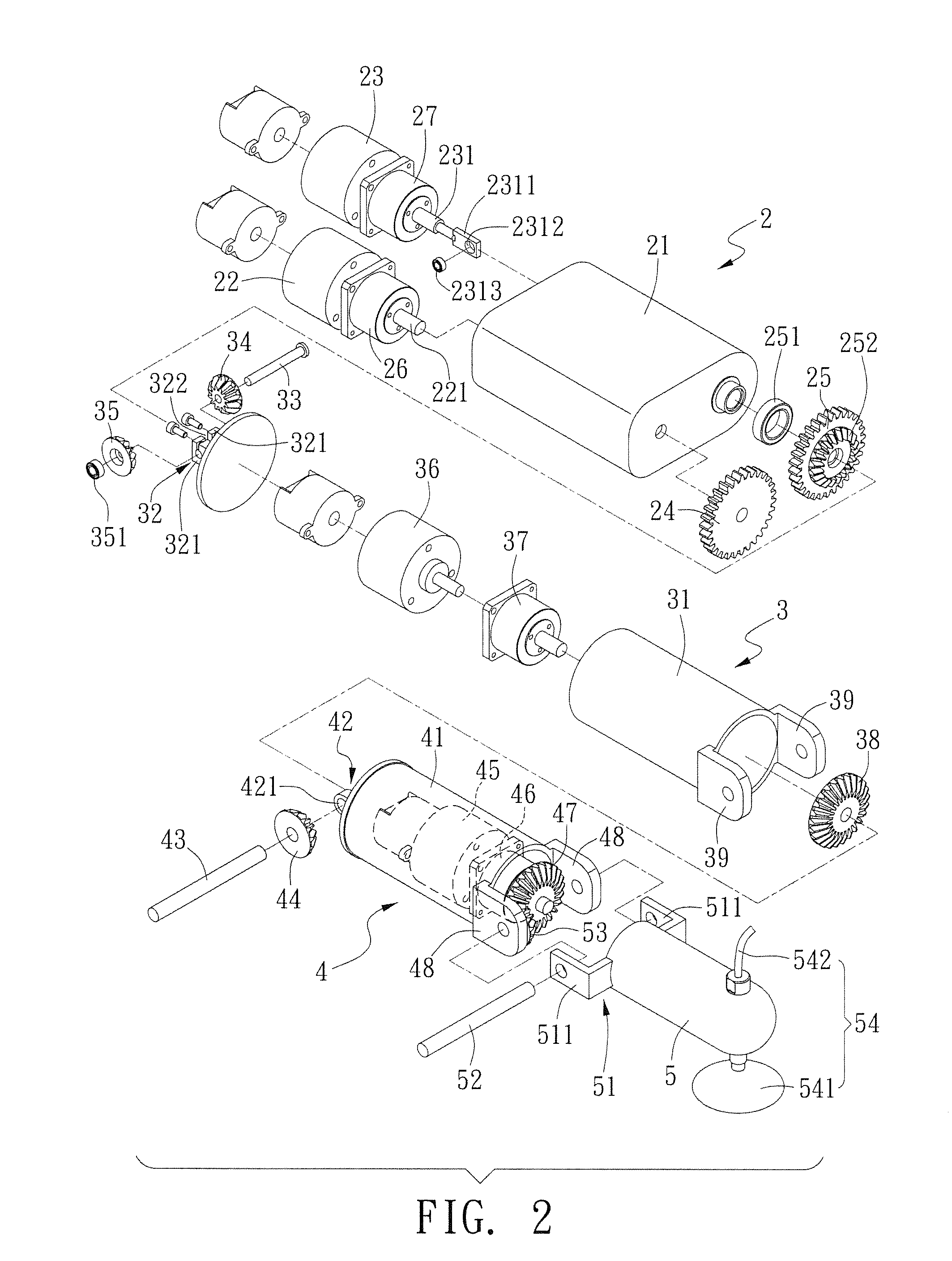
[0017]The start joint shaft 2 is extended from the palm base 1 and has a casing 21, and a first motor 22 and a second motor 23 installed on adjacent sides of the casing 21 respectively, wherein a first transmission shaft 221 is extended from the first motor 22, and a second transmission shaft 231 is extended ...


PUM


Abstract

An end effector module includes a palm base and robotic fingers extended from the palm base. Each robotic finger is composed of four joint shafts pivotally coupled with one another, and one of the four joint shafts, namely a start joint shaft, has a driving mechanism for driving a corresponding robotic finger to rotate, and each joint shaft has a driving mechanism to drive a next corresponding joint shaft to turn pivotally and bend with respect to other corresponding joint shafts, so that each robotic finger is module with four degrees of freedom for fine-tuning the position of a suction device installed at an end joint shaft, and the suction device can move along the normal direction of a suction point selected on the surface of a clamped object to achieve the effect of clamping and sucking an object securely without the risk of being loosened easily.

Description

FIELD OF THE INVENTION[0001]The present invention relates to an end effector module, in particular to the end effector module having a plurality of joint shafts and a driving device installed at each joint shaft and provided for driving and fine-tuning the joint shafts to facilitate clamping and sucking an object from different oriented surfaces.BACKGROUND OF THE INVENTION[0002]In a conventional end effector structure as disclosed in U.S. Pat. No. 5,501,498, the frictional force between an end joint shaft of a robotic finger and an object is used for clamping the object, but the clamping effect is relatively low due to factors such as the clamping angle, the size and the surface smoothness of the object.[0003]In another conventional end effector structure as disclosed in U.S. Pat. Publication No. 2010 / 0156125, a combination of air pressure, a link rod and a spring is provided to drive a robotic finger to turn pivotally in order to achieve the operation of clamping an object, and the...

Claims


Application Information

Patent Timeline
IPC IPC(8): B25J15/06B25J15/00
CPCB25J15/0009B25J15/0616
Inventor WANG, PEI-JUIWU, CHE-HAU
Owner PRECISION MACHINERY RES & DEV CENT
Why Eureka
Try Eureka