Touch panel and display device comprising the same

Active Publication Date: 2014-07-17
TIANMA MICRO ELECTRONICS CO LTD
View PDF11 Cites 10 Cited by
  • Summary
  • Abstract
  • Description
  • Claims
  • Application Information

AI Technical Summary

Benefits of technology

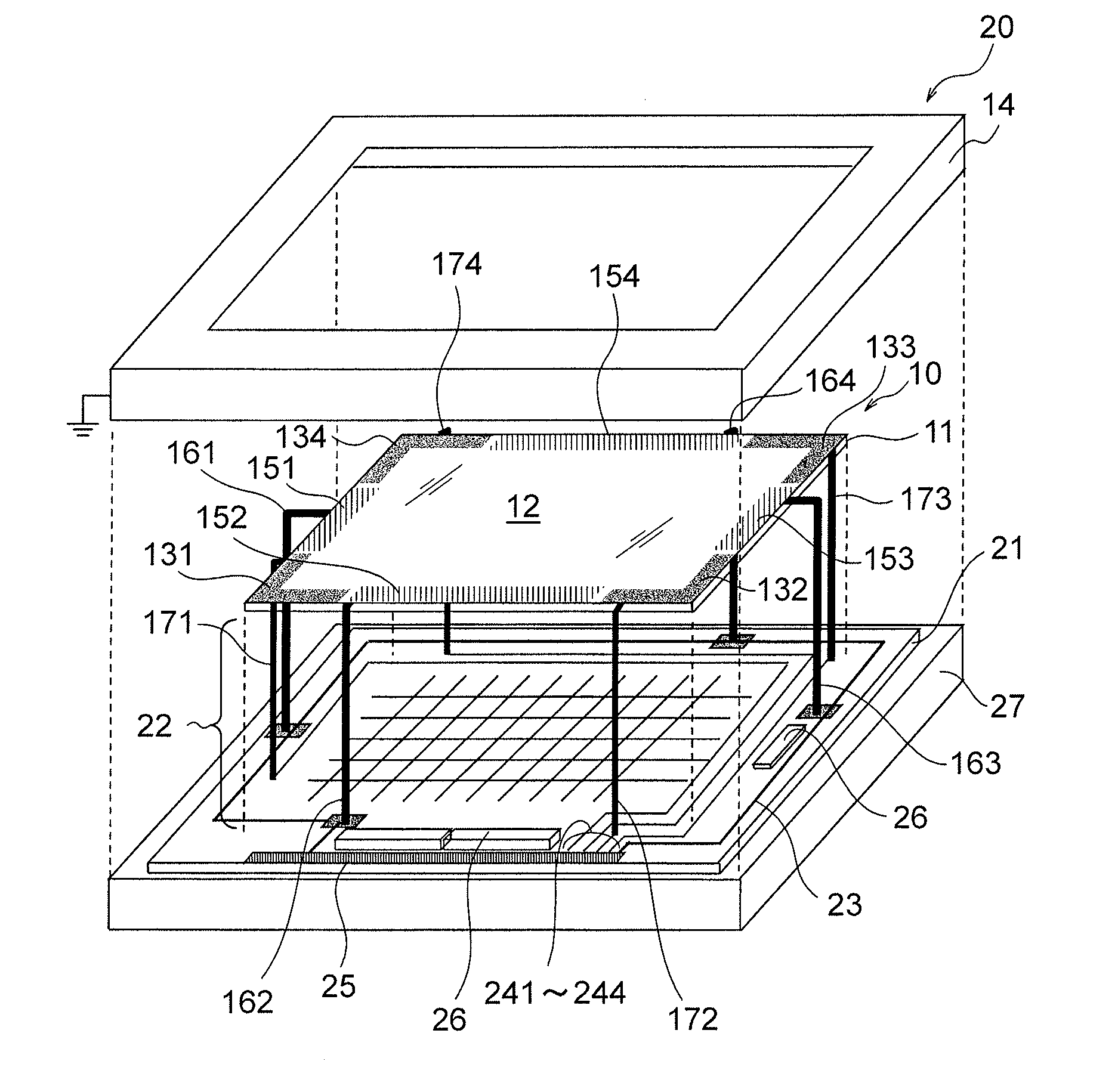
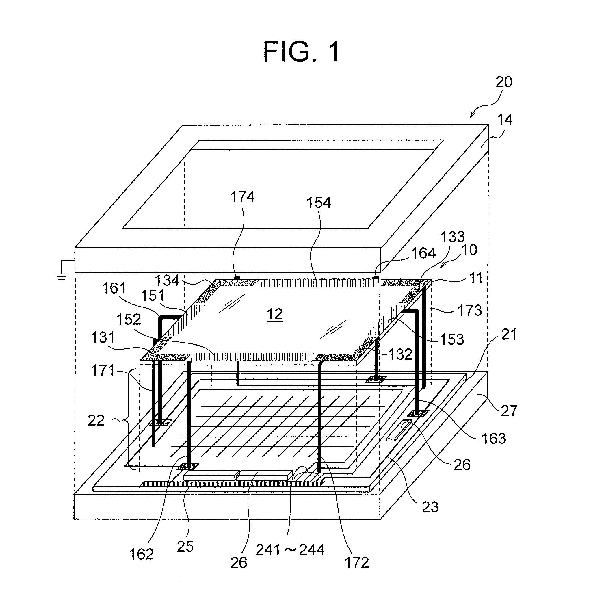
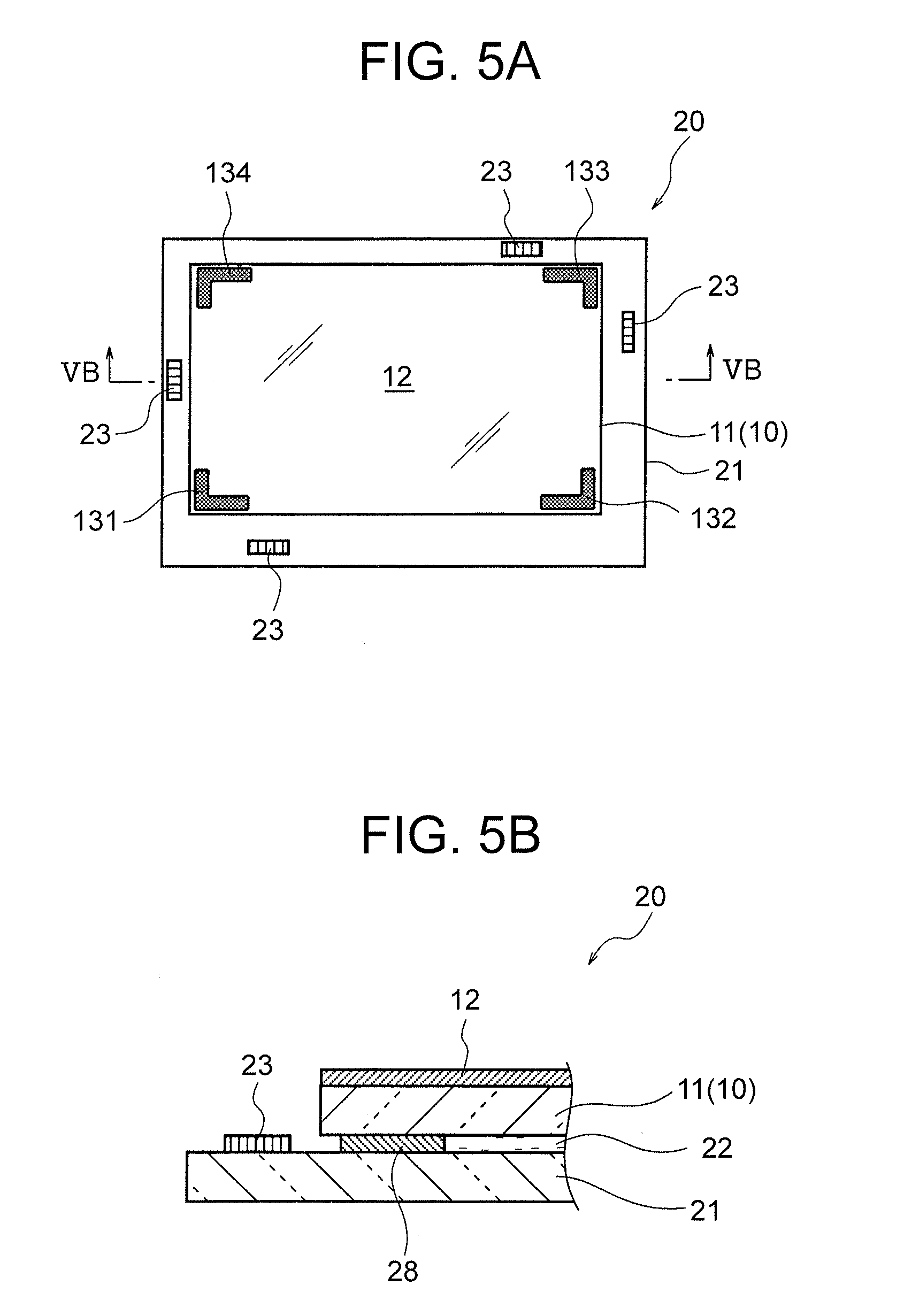
[0014]The touch panel according to an exemplary aspect of the invention includes: a substrate; a detection region formed in a center side of the substrate, which generates a detection signal according to a contact position of a conductor; a plurality of detection electrodes formed in a fringe side of the substrate, which output the detection signal generated in the detection region; a conductive frame that covers above an outer side of the detection region on the substrate; and a shield electrode formed on the outer side of the detection region and between each of the plurality of detection electrodes, to which a shield signal that shields an electric influence for the detection region is supplied, wherein distance from the detection region to the shield electrode is shorter than distance from the detection region to the conductive frame.

Problems solved by technology

However, there are following issues regarding the related technique 2.

Method used


Image

  • Touch panel and display device comprising the same
  • Touch panel and display device comprising the same
  • Touch panel and display device comprising the same

Examples


Embodiment Construction

of the touch sensor and the display device according to the first exemplary embodiment;

[0031]FIG. 16 is a plan view showing Modification Example 2 of the touch sensor and the display device according to the first exemplary embodiment;

[0032]FIG. 17 is a plan view showing Modification Example 3 of the touch sensor and the display device according to the first exemplary embodiment;

[0033]FIG. 18 is a plan view showing Modification Example 4 of the touch sensor according to the first exemplary embodiment;

[0034]FIG. 19 is a sectional view showing a part of a section taken along a line XIX-XIX of FIG. 18;

[0035]FIG. 20 is a sectional view showing a part of a section taken along a line XX-XX of FIG. 18;

[0036]FIG. 21 is a plan view showing a touch panel and a display device according to a second exemplary embodiment;

[0037]FIG. 22 is a sectional view taken along a line XXII-XXII of FIG. 21;

[0038]FIG. 23 is a plan view showing a touch panel and a display device according to a third exemplary em...


PUM


Abstract

To shield the noise generated due to deformation or the like of the conductive frame. The touch panel includes: a detection region which generates detection signals according to a contact position of a conductor; a plurality of detection electrodes which output detection signals generated in the detection region; a conductive frame which covers above the outer side of the detection region and above the detection electrode; and shield electrodes formed on the outer side of the detection region on the CF substrate and between each of the plurality of detection electrodes, to which shield signals for shielding the electric influence on the detection region and the detection electrodes are supplied. Further, the distance between the shield electrodes and the detection region is shorter than distance between the conductive frame and the detection region.

Description

CROSS-REFERENCE TO RELATED APPLICATION[0001]This application is based upon and claims the benefit of priority from Japanese patent application No. 2013-004722, filed on Jan. 15, 2013, the disclosure of which is incorporated herein in its entirety by reference.BACKGROUND OF THE INVENTION[0002]1. Field of the Invention[0003]The present invention relates to a touch panel with which information is inputted by touching the panel with a finger or the like and to a display device having the touch panel.[0004]2. Description of the Related Art[0005]Recently, a display device with a touch panel acquired by combining the touch panel to a display input device such as a ticket-vending machine is being broadly put into practical use. With the display device having the touch panel, buttons to be touched are displayed on the display device. When those parts are pressed by a finger or the like, the fact that it is being pressed is detected and information is inputted. Further, the display device swi...

Claims


Application Information

Patent Timeline
Patent Type & Authority Applications(United States)
IPC IPC(8): G06F3/041
CPCG06F3/041G06F3/0443G06F3/0444G06F2203/04103G06F2203/04107
Inventor YOSHIDA, HITOSHI
Owner TIANMA MICRO ELECTRONICS CO LTD
Why Eureka
Try Eureka