
Capacitive force sensing touch panel

A touch panel, capacitive technology, applied in the direction of electrical digital data processing, instrumentation, data processing input/output process, etc., can solve the problem that capacitive touch panels are difficult to obtain pressure sensing results, pressure sensing distortion, capacitance Sensing volume changes, etc.

Inactive Publication Date: 2017-02-22
RAYDIUM SEMICON
View PDF3 Cites 4 Cited by
  • Summary
  • Abstract
  • Description
  • Claims
  • Application Information

AI Technical Summary

Problems solved by technology

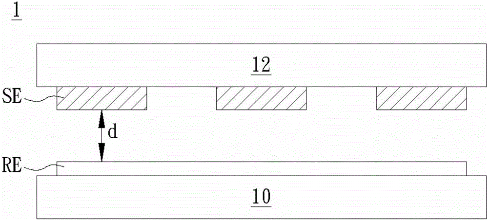
[0004] However, the capacitive touch sensing signal will also change with the pressing area of ​​the finger. Therefore, when the finger presses down, the pressing area will increase, which will also change the capacitance sensing value, which will lead to the same capacitance change. The quantity is the pressure sensing distortion of the judging signal, so it is difficult to obtain more accurate pressure sensing results using the traditional stacked structure 1 capacitive touch panel

Method used


Image

  • Capacitive force sensing touch panel
  • Capacitive force sensing touch panel
  • Capacitive force sensing touch panel

Examples


Embodiment Construction

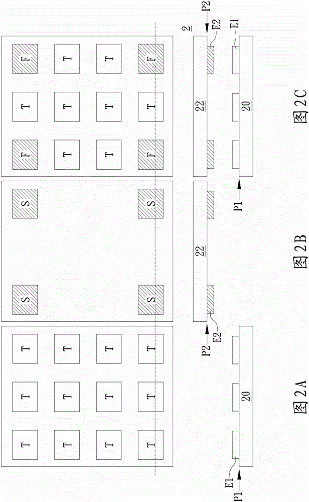
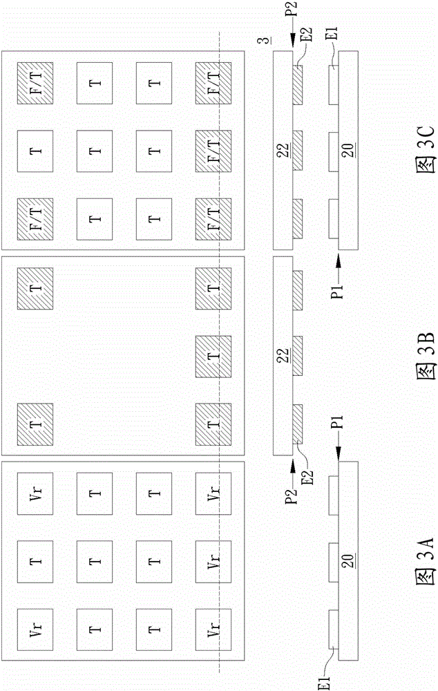
[0104] A specific embodiment according to the present invention is a capacitive pressure sensing touch panel. In this embodiment, the capacitive pressure sensing touch panel of the present invention can have different touch panel structures such as in-cell, on-cell or out-cell, and can be shielded by arranging opposite upper electrodes or Dividing the electrodes into touch-sensing electrodes and pressure-sensing electrodes according to their functions effectively prevents the capacitive sensing value from being distorted by the change of finger pressing area during pressure sensing, thereby improving the deficiencies of the prior art.

[0105] First, please refer to FIG. 2A to FIG. 2C , in this embodiment, the capacitive pressure sensing touch panel includes a plurality of pixels. The stacked structure 2 of each pixel includes a first substrate 20 , a second substrate 22 , a plurality of first electrodes E1 and a plurality of second electrodes E2 . Wherein, the plurality of f...


PUM


Abstract

A capacitive force sensing touch panel is disclosed. The capacitive force sensing touch panel includes a plurality of pixels. A laminated structure of each pixel includes a first plane, a second plane, at least a first electrode and at least a second electrode. The second plane is disposed above the first plane and parallel to the first plane. The at least one first electrode is disposed on the first plane. The at least one second electrode is disposed on the second plane. The at least one first electrode and the at least one second electrode are selectively driven as touch sensing electrodes or force sensing electrodes respectively.

Description

technical field [0001] The present invention relates to touch panels, in particular to a capacitive pressure-sensing touch panel. Background technique [0002] Generally speaking, traditionally, capacitive touch electrodes in capacitive touch panels are also used as pressure sensing electrodes, such as figure 1 In the stacked structure 1 shown, the sensing electrodes SE are disposed on the upper substrate 12 , and the reference electrodes RE disposed on the lower substrate 10 may be used. [0003] When the upper substrate 12 is pressed by a finger, since the distance d between the sensing electrode SE of the upper substrate 12 and the reference electrode RE of the lower substrate 10 will change with the pressing force of the finger, the sensing electrode SE and the reference electrode RE The capacitive sensing value between them also changes accordingly. [0004] However, the capacitive touch sensing signal will also change with the pressing area of ​​the finger. Therefore...

Claims


Application Information

Patent Timeline
Patent Type & Authority Applications(China)
IPC IPC(8): G06F3/044G06F3/041
CPCG06F3/0414G06F3/044G06F3/0412G06F3/04166G06F3/0445G06F3/0446G06F3/0447
Inventor 李昆倍林依萦谢欣玮江昶庆许有津
Owner RAYDIUM SEMICON
Learn More