Light emitting device and light sheet

a light-emitting device and light-emitting sheet technology, which is applied in semiconductor devices, lighting and heating apparatuses, instruments, etc., can solve the problems of low light extraction efficiency of organic el devices, inability to achieve 100% extraction efficiency, and inability to efficiently extract light in every direction. achieve the effect of reducing luminance unevenness and color unevenness, improving light extraction efficiency, and reducing the effect of unevenness

Active Publication Date: 2014-07-24
SAMSUNG DISPLAY CO LTD
View PDF5 Cites 11 Cited by
  • Summary
  • Abstract
  • Description
  • Claims
  • Application Information

AI Technical Summary

Benefits of technology

[0011]A light-emitting device according to an implementation of the present invention includes a diffraction grating structure and a diffusion layer, whereby light extraction efficiency is improved and luminance unevenness and color unevenness can be effectively reduced.

Problems solved by technology

Thus, generally speaking, an organic EL device does not have a high efficiency of light utility.
However, since the effect of interference depends on the direction in which generated light propagates, light in every direction cannot be efficiently extracted.
Therefore, this method cannot attain a 100% extraction efficiency.
Moreover, since the interference of light depends on wavelength, it is difficult to efficiently extract light of all wavelengths within the emission wavelength region.
In the case of a white-color organic EL device, this causes luminance unevenness or color unevenness, where luminance or color changes depending on the angle of viewing.

Method used


Image

  • Light emitting device and light sheet
  • Light emitting device and light sheet
  • Light emitting device and light sheet

Examples


first embodiment

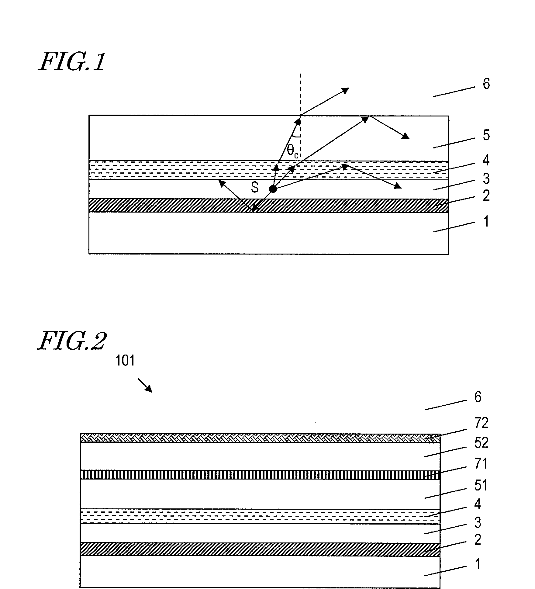
[0041]FIG. 2 schematically shows a cross-sectional structure of a first embodiment of the light-emitting device according to the present invention. The light-emitting device 101 includes an electrode 2 provided on a substrate an emission layer 3 located on the electrode 2, an electrode 4 located on the emission layer 3, a layer 51 located on the electrode 4, a diffraction grating structure 71 located on the layer 51, a layer 52 located on the diffraction grating structure 71, and a diffusion layer 72 located on the layer 52.

[0042]The present embodiment is effective for suppressing color unevenness, and therefore provides a particularly outstanding effect when using an emission layer 3 that emits white light. An example of a light-emitting device in which such an emission layer 3 is used may be a light-emitting device that incorporates an organic EL device, for example. In the case of organic EL, the emission layer 3 may sometimes be composed of plural layers in order to obtain a hig...

second embodiment

[0079]FIG. 15 schematically shows a cross-sectional structure of a second embodiment of the light-emitting device according the present invention. The light-emitting device 103 differs from the first embodiment in that a layer 53 which is located on the diffusion layer 72 is further included, the layer 53 being an air layer 6. The layer 53 is a protection layer for protecting the diffusion layer 72 from the exterior, for example.

[0080]When the diffusion layer 72 has its light-diffusing structure inside the diffusion layer 72, it is effectively as though the layer 53 also existed.

[0081]Therefore, even when the layer 53 is further included, this is essentially regardable as a diffusion layer in which the diffusion layer 72 and the layer 53 are integrated. The light-emitting device of the present embodiment provides similar effects to those of the first embodiment, although light may possibly be absorbed in the layer 53, causing a loss on the order of a few %

third embodiment

[0082]FIG. 16 schematically shows a cross-sectional structure of a third embodiment of the light-emitting device according to the present invention. The light-emitting device 104 differs from the first embodiment in that the diffraction grating structure 71 and the diffusion layer 72 are switched in position, and that the electrode 2 is reflective.

[0083]Since the diffraction grating structure 71 and the diffusion layer 72 are switched in position, the diffusion layer 72 is located between the diffraction grating structure and the emission layer 3 in the present embodiment. Moreover, the electrode 2 has a structure that reflects light going out from the emission layer 3.

[0084]Therefore, with the light-emitting device 104, light which is reflected by the diffraction grating structure 71 and the diffusion layer 72 toward the emission layer 3 side is again reflected toward the diffusion layer 72 by the electrode 2, and allowed to go out to the exterior. In this case, the light which is ...


PUM


Abstract

A light-emitting device disclosed herein includes: an emission layer; a diffraction grating structure including a diffraction grating; and a diffusion layer having a structure for diffusing light which is transmitted from one face to another face. The light going out from the emission layer has a central wavelength λ. The diffraction grating has a period p which is not less than 1.0λ and not more than 3.5λ. The diffusion layer has a haze of 80% or more and a total light transmittance of 80% or less.

Description

TECHNICAL FIELD[0001]The present application relates to a sheet and a light-emitting device including the same.BACKGROUND ART[0002]In recent years, organic electro-luminescence (organic EL) devices are drawing attention as one kind of light-emitting device with a high emission efficiency. FIG. 1 schematically shows a cross-sectional structure of a generic organic EL device. The conventional organic EL device is structured so that an electrode 2, an emission layer 3, a transparent electrode 4, and a transparent substrate 5 are stacked on a substrate 1. The transparent substrate 5 is in contact with an air layer 6. By applying a voltage between the electrode 2 and the transparent electrode 4, the illuminant emits light at a point S in the interior of the emission layer 3. Within the generated light, a portion intactly propagates along the direction of the air layer 6, while a portion is reflected at the electrode 2 and then propagates along the direction of the air layer 6. When light...

Claims


Application Information

Patent Timeline
Patent Type & Authority Applications(United States)
IPC IPC(8): F21K99/00
CPCF21K9/50G02B5/0252G02B5/0278H10K50/854
Inventor INADA, YASUHISANISHIWAKI, SEIJI
Owner SAMSUNG DISPLAY CO LTD
Why Eureka
Try Eureka