Subminiature optical system and portable device including the same
Active Publication Date: 2014-07-24
SAMSUNG ELECTRO MECHANICS CO LTD
View PDF8 Cites 97 Cited by
Summary
Abstract
Description
Claims
Application Information
AI Technical Summary
This helps you quickly interpret patents by identifying the three key elements:
Problems solved by technology
Method used
Benefits of technology
Benefits of technology
The present invention provides a small optical system with high resolution and a compact shape. It is made up of only five sheets of lenses, making it short and lightweight. The technical effect of this invention is that it can be used in a portable device.
Problems solved by technology
However, it may be difficult to satisfy the requirements for a desired level of optical performance due to a lack of design freedom resulting therefrom.
However, the wide-angle optical system is suitable for capturing images having wide backgrounds, but is not suitable for imaging a subject by zooming in on a distant object.
Method used
Image
Click on the blue label to locate the original text in one second.
Reading with bidirectional positioning of images and text.
Examples
embodiment 1
[0071]The following Table 1 shows examples of numerical values according to a first embodiment of the present invention.
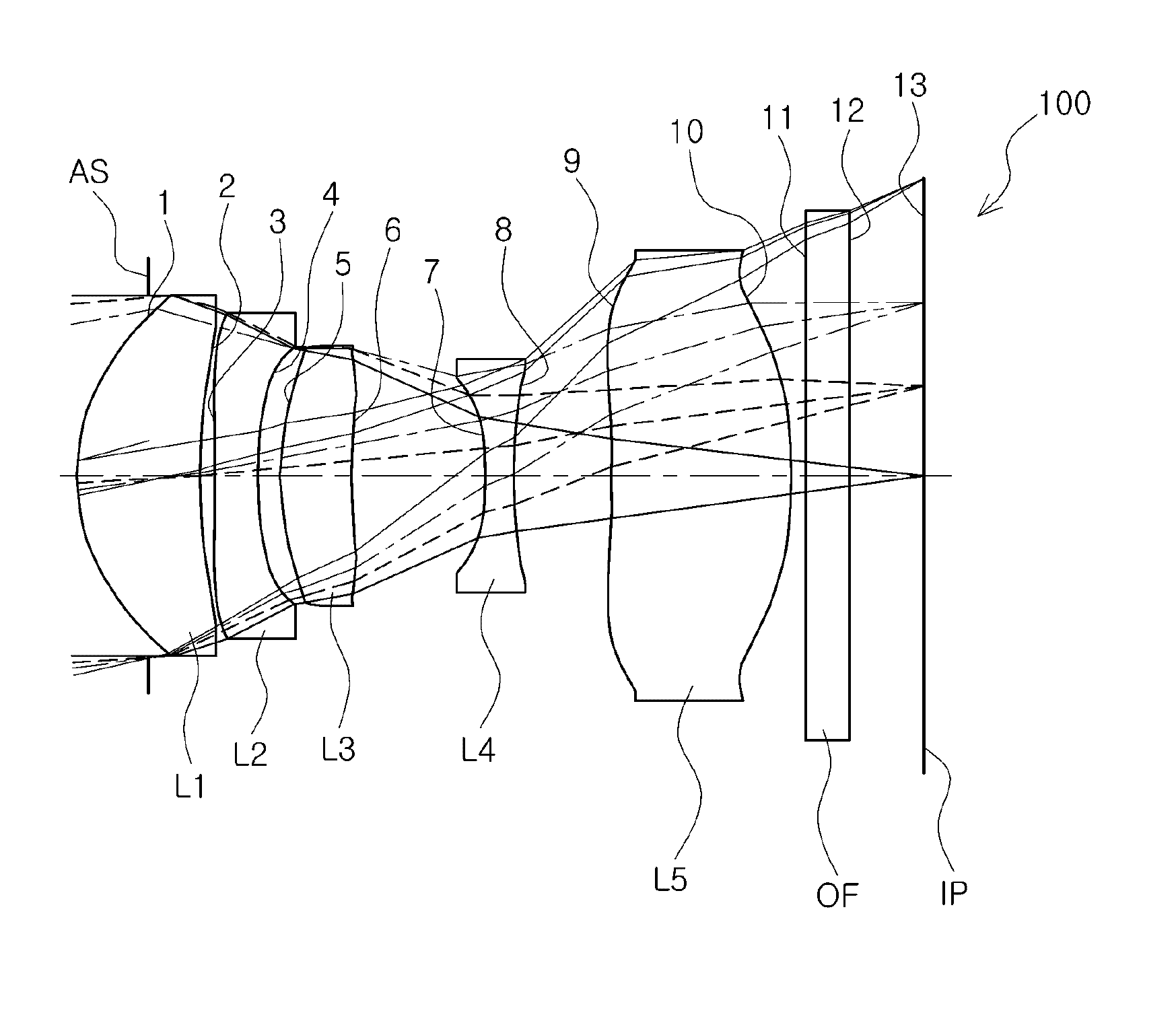
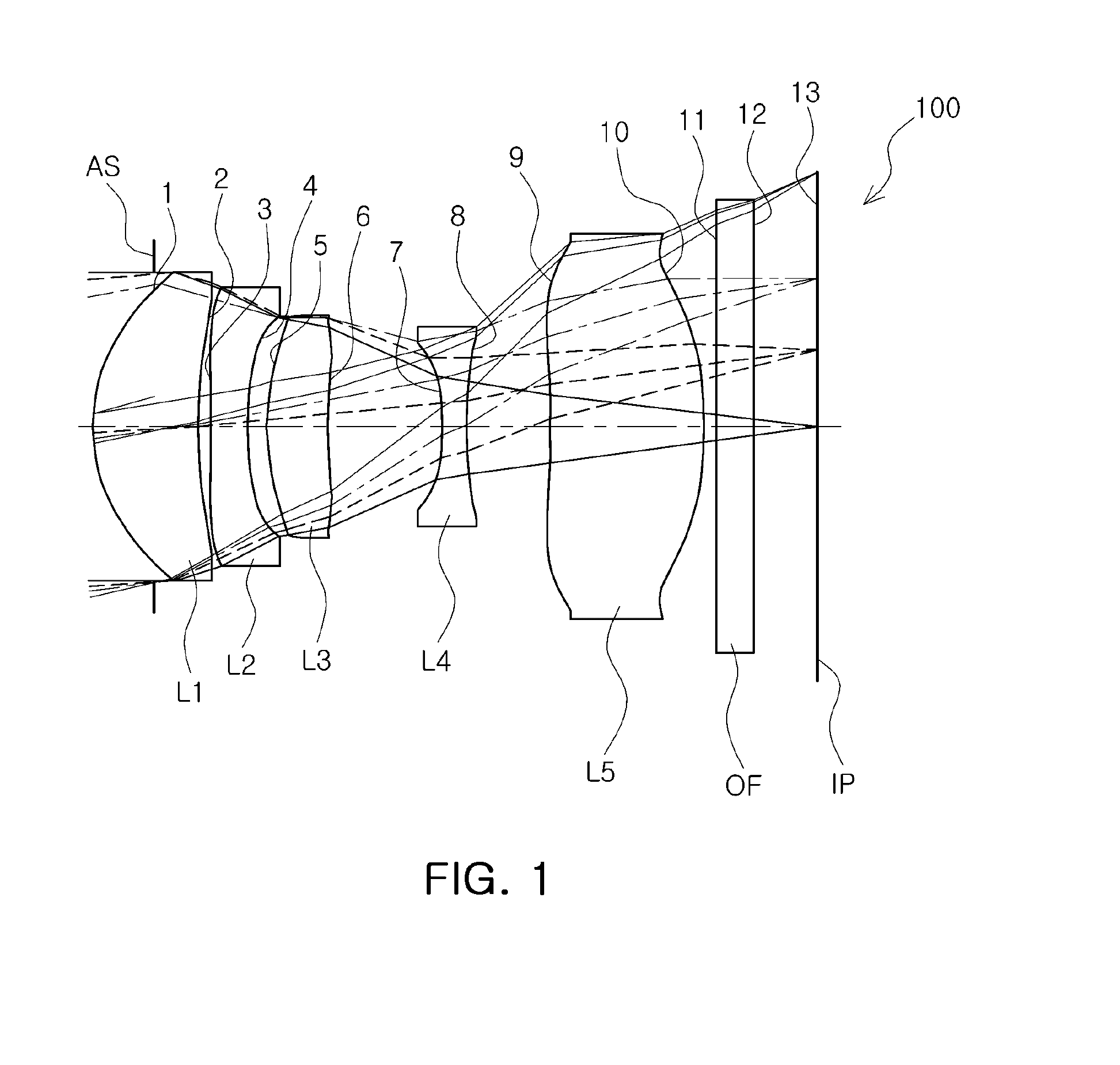
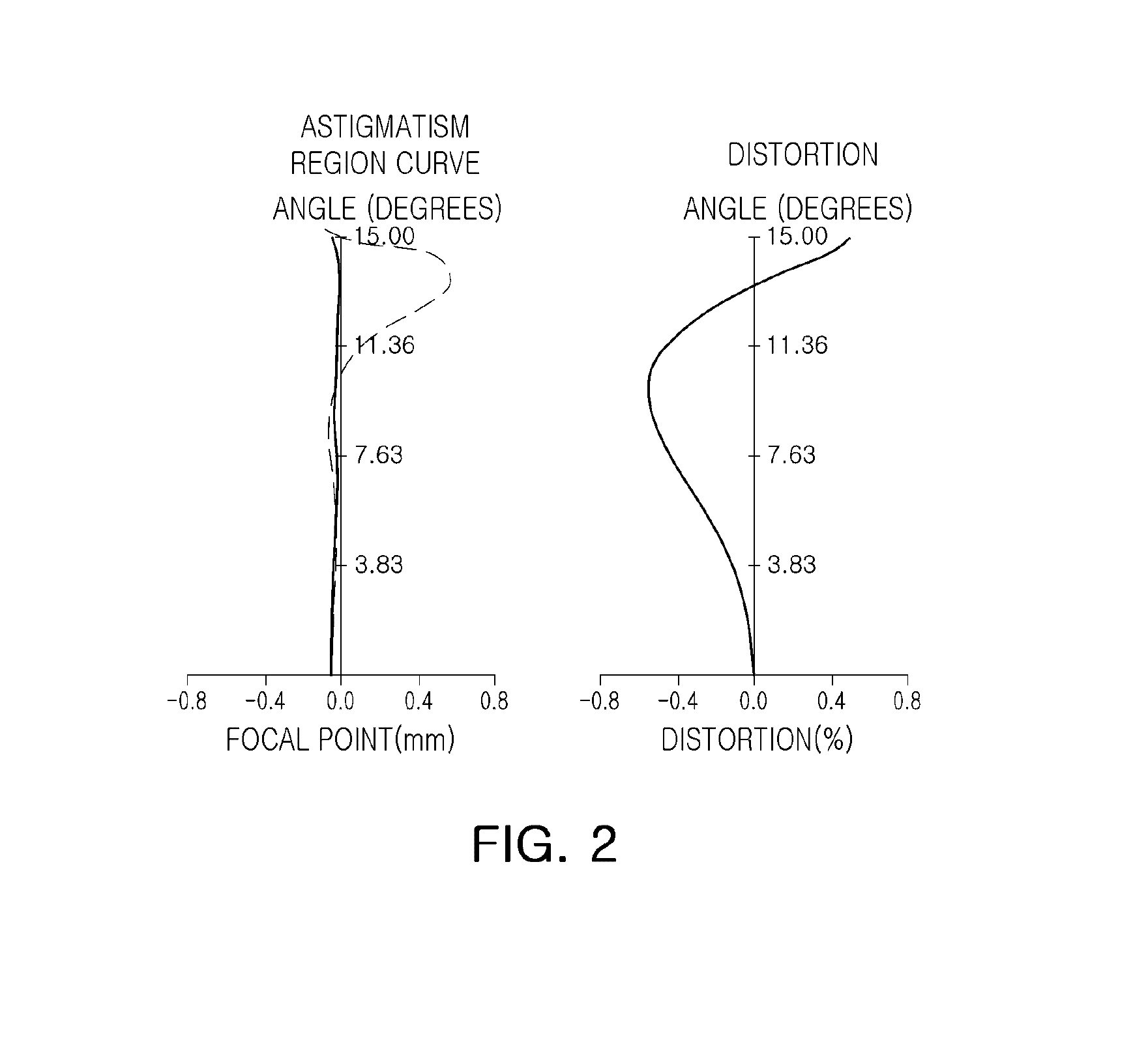
[0072]FIG. 1 is the configuration diagram of a lens showing lens disposition of a subminiature optical system according to the first embodiment of the present invention; and FIGS. 2 and 3 show aberration characteristics of the subminiature optical system shown in Table 1 and FIG. 1.
[0073]In the subminiature optical system according to the first embodiment of the present invention, F number FNo is 2.8, the view angle is 30 degrees, the entire focal distance F is 7 mm, the focal distance F1 of the first lens is 3.57 mm, the focal distance F2 of the second lens is −4.18 mm, the focal distance F3 of the third lens is 4.35 mm, the focal distance F4 of the fourth lens is −2.43 mm, and the focal distance F5 of the fifth lens is 14.18 mm.
[0074]In addition, the distance TTL from an object side surface of the first lens to the image plane is 5.8 mm.
TABLE 1SurfaceRadius ofThi...
embodiment 2
[0076]The following Table 3 shows examples of numerical values according to a second embodiment of the present invention.
[0077]In addition, FIG. 4 is a configuration diagram of a lens showing lens disposition of a subminiature optical system 200 according to the second embodiment of the present invention; while FIGS. 5 and 6 show aberration characteristics of the subminiature optical system shown in Table 3 and FIG. 4.
[0078]In the second embodiment of the present invention, F number FNo is 2.8, the view angle is 28 degrees, the entire focal distance F of the optical system is 7.5 mm, the focal distance F1 of the first lens is 3.6 mm, the focal distance F2 of the second lens is −5.35 mm, the focal distance F3 of the third lens is 6.6 mm, the focal distance F4 of the fourth lens is −3.1 mm, and the focal distance F5 of the fifth lens is −16 mm.
[0079]In addition, the distance TTL from an object side surface of the first lens to the image plane is 6 mm.
TABLE 3SurfaceRadius ofRefractive ...
PUM
Abstract
There are provided a subminiature optical system having a miniature size and capable of obtaining a narrow view angle using only five sheets of lenses, and a portable device having the same. The subminiature optical system includes a first lens convex toward the object side and having positive refractive power. a second lens concave toward an image side and having negative refractive power, a third lens convex toward the object side and having positive refractive power, a fourth lens concave toward the image plane and having negative refractive power, and a fifth lens convex toward the image plane and having negative or positive refractive power, sequentially from an object side.
Description
CROSS-REFERENCE TO RELATED APPLICATION[0001]This application claims the priority of Korean Patent Application No. 10-2013-0007047 filed on Jan. 22, 2013, in the Korean Intellectual Property Office, the disclosure of which is incorporated herein by reference.BACKGROUND OF THE INVENTION[0002]1. Field of the Invention[0003]The present invention relates to a subminiature optical system and a portable device including the same, and more particularly, to a subminiature optical system having a subminiature size, capable of obtaining a narrow view angle using five sheets of lenses and a portable device including the same.[0004]2. Description of the Related Art[0005]Initial portable terminals only included a communications function. However, in accordance with an increase in the usage of portable terminals, various functions such as image capturing and the ability to transmit images via communications networks have been implemented in portable terminals. Therefore, functions of, and services...
Claims
Application Information
Patent Timeline
Application Date:The date an application was filed.
Publication Date:The date a patent or application was officially published.
First Publication Date:The earliest publication date of a patent with the same application number.
Issue Date:Publication date of the patent grant document.
PCT Entry Date:The Entry date of PCT National Phase.
Estimated Expiry Date:The statutory expiry date of a patent right according to the Patent Law, and it is the longest term of protection that the patent right can achieve without the termination of the patent right due to other reasons(Term extension factor has been taken into account ).
Invalid Date:Actual expiry date is based on effective date or publication date of legal transaction data of invalid patent.

