Electrical connector

a technology of electrical connectors and connectors, applied in the direction of coupling devices, two-part coupling devices, electrical apparatus, etc., can solve the problem that only the sort of low-rise mixed electrical connectors is applicable, and achieve the effects of improving the performance of electrical connectors, enhancing air circulation in power systems, and saving the edge space of circuit boards

Active Publication Date: 2014-07-24
OUPIN ELECTRONICS KUNSHAN
View PDF3 Cites 13 Cited by
  • Summary
  • Abstract
  • Description
  • Claims
  • Application Information

AI Technical Summary

Benefits of technology

[0020]Compared with conventional technologies the present invention includes following advantages: the power receptacle body and signal plug body in the electrical connector according to the present invention are both designed to be upright or vertical so as to save the edge space of a circuit board and allowing a larger number of connecter ports of same or other kinds to be mounted onto the edge of the circuit board; the electrical connector according to the present invention includes a char...

Problems solved by technology

Therefore, this sort of low-rise mixed electrical connectors is only applicable in an electronic device that has a strict control on ...

Method used


Image

  • Electrical connector
  • Electrical connector
  • Electrical connector

Examples


Embodiment Construction

[0027]The following embodiments are exemplified by referring to the accompanying drawings, for describing specific embodiments implemented by the present invention. Furthermore, directional terms described by the present invention, such as upper, lower, front, back, left, right, inner, outer, side and etc., are only directions by referring to the accompanying drawings, and thus the used directional terms are used to describe and understand the present invention, but the present invention is not limited thereto.

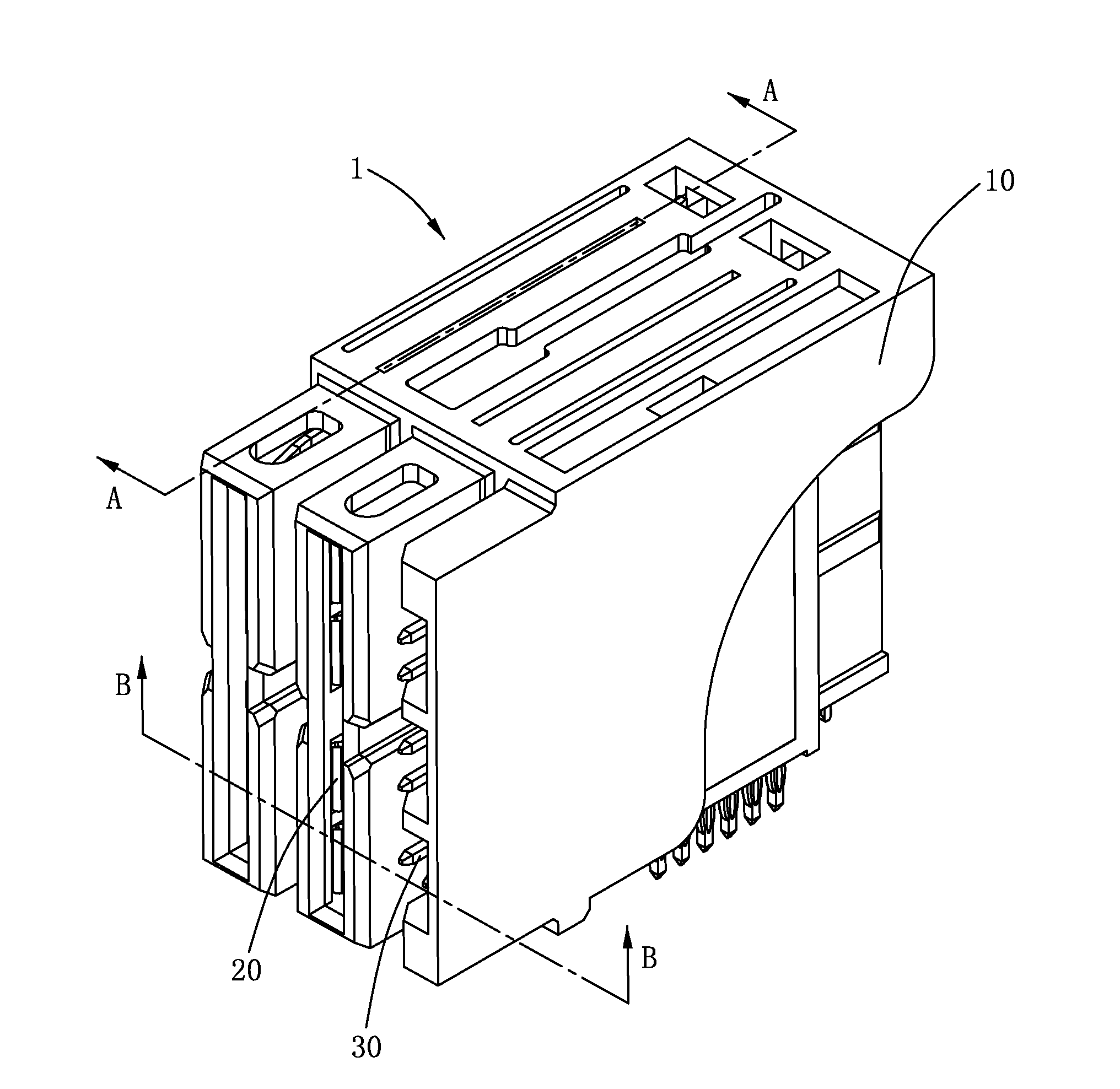
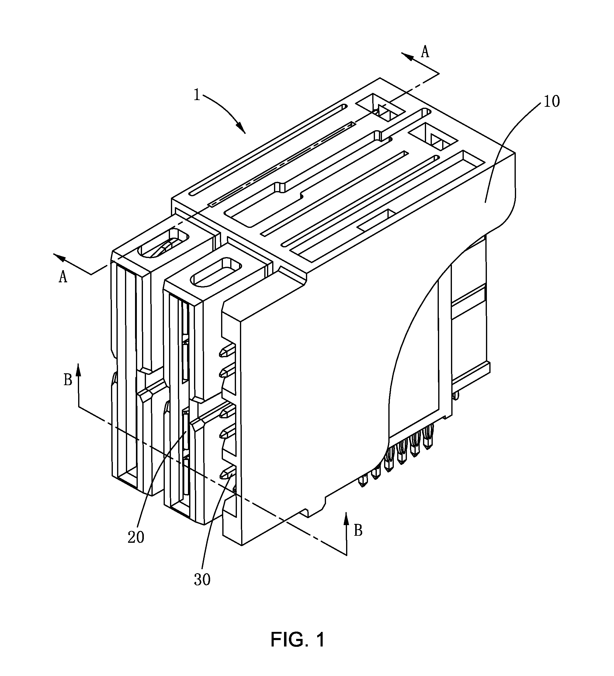
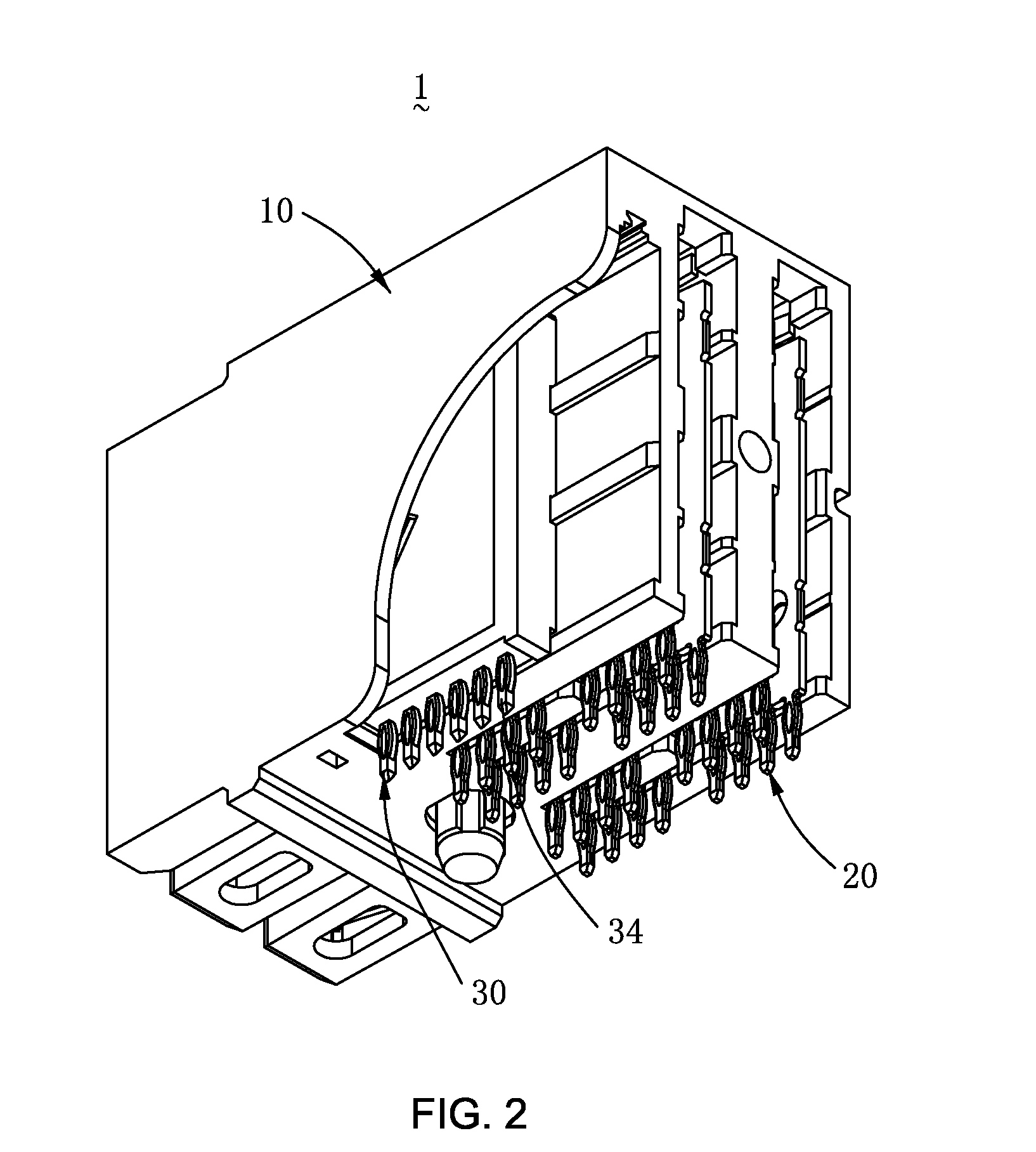
[0028]Please refer to the electrical connector 1 illustrated in FIGS. 1 to 6 according to the present invention, wherein FIG. 1 is a perspective view of the electrical connector 1 according to the present invention; FIG. 2 is a perspective view of the electrical connector 1 according to the present invention, which is from another angle; FIG. 3 is an exploded diagram of the electrical connector 1 according to the present invention; FIG. 4 is an exploded diagram of the electric...


PUM


Abstract

An electrical connector is provided in the present invention, including an insulating housing, multiple power terminals and multiple signal terminals. The insulating housing has at least one upright power receptacle body and at least one upright signal plug body parallel to the power receptacle body. Wherein the power receptacle body forms an upright power port on a front surface thereof, and the signal plug body forms at least one signal port on a front surface thereof. Each power terminal has a plate-shaped base plate, at least one spring connection end and multiple tails. The power receptacle body and the signal plug body of the present invention are designed to be upright for saving the edge space of a circuit board. Moreover, the electrical connector of the present invention also has a character of zero insertion force by controlling the length of the signal terminal and the power terminal.

Description

CROSS REFERENCE TO RELATED APPLICATION[0001]This application claims the priority of Chinese Patent Application No. 201310019996.6, filed on Jan. 21, 2013 in the SIPO (State Intellectual Property Office of the P.R.C.).BACKGROUND OF THE INVENTION[0002]1. Field of the Invention[0003]The present invention relates to a connector technical field, and particularly relates to a compact electrical connector that is power and signal mixed.[0004]2. Description of Prior Art[0005]An electrical connector includes electrical features of durable and convenient and is applicable in various industrial and commercial usages such as a power supply, a server, a router, a storage device, an industrial controller and a modular chassis etc. In the meanwhile, since several terminal configurations can be designed in the connector, applications of power source, signal and the combination thereof can be satisfied.[0006]At present, there are a great many of manufacturers striving to introduce electrical connect...

Claims


Application Information

Patent Timeline
IPC IPC(8): H01R13/516
CPCH01R13/516H01R12/7088H01R12/724H01R13/113H01R2107/00
Inventor CHEN, HSIN CHIH
Owner OUPIN ELECTRONICS KUNSHAN
Why Eureka
Try Eureka