electrical connector

A technology of electrical connectors and power interfaces, which is applied in the field of compact electrical connectors, can solve the problems of limited space on the edge of the circuit board, cannot meet the scalability of the edge space of the circuit board, and occupy the edge space of the circuit board, so as to save the edge space , Increase applicability, effect of compact structure

Active Publication Date: 2016-08-24
OUPIN ELECTRONICS KUNSHAN
View PDF4 Cites 0 Cited by
  • Summary
  • Abstract
  • Description
  • Claims
  • Application Information

AI Technical Summary

Problems solved by technology

For example, U.S. Patent No. 6,319,075 discloses an electrical connector, and only the power module is designed with a large width dimension. This elongated design will take up too much edge space of the circuit board. The edge space is limited, so it is not possible to expand a larger number of other types of connectors
Therefore, this hybrid electrical connector can only be used in electronic equipment that strictly controls the height of the electrical connector, but cannot meet the requirements for the scalability of the edge space of the circuit board.

Method used


Image

  • electrical connector
  • electrical connector
  • electrical connector

Examples


Embodiment Construction

[0038] The following description of the embodiments refers to the accompanying drawings to illustrate specific embodiments in which the invention may be practiced. The directional terms mentioned in the present invention, such as "up", "down", "front", "back", "left", "right", "top", "bottom", etc., are only for reference to the attached drawings. direction. Therefore, the directional terms used are used to illustrate and understand the present invention, but not to limit the present invention.

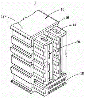
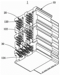
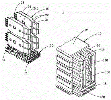
[0039] Please refer to Figure 1 to Figure 7 The electrical connector 1 of the present invention shown, figure 1 It is a schematic diagram of the three-dimensional structure of the first embodiment of the electrical connector 1 of the present invention, figure 2 for figure 1 Shown is a schematic diagram of the three-dimensional structure of the electrical connector 1 of the present invention in another direction, image 3 for figure 1 Shown is an exploded view of the electrical...


PUM


Abstract

The invention discloses an electrical connector including an insulation body, a power terminal and a signal terminal. The insulation body has an upright insulation pedestal, two upright power socket bodies protruding forward side by side and in parallel from the front surface of the insulation pedestal, and at least one flat signal socket body protruding forward from the front surface of the insulation pedestal and forming an up-and-down superposed structure with the two power socket bodies. The power terminal includes two conductive strips which are symmetrical and independent. According to the electrical connector, the power socket bodies are designed into an upright or vertical structure, and the signal socket body is arranged to form an up-and-down superposed structure with the power socket bodies, so that a more compact structure is formed, the edge space of a circuit board can be saved, and more interfaces of connectors of different types or the same type can be installed at the edge of the circuit board. In addition, a separated design is adopted to increase the applicability of the electrical connector.

Description

technical field [0001] The invention relates to the technical field of connectors, in particular to a compact electrical connector in which power and signals are mixed. Background technique [0002] Currently, electrical connectors are used in various industrial and commercial applications, such as power supplies, servers, routers, storage, industrial controllers, modular enclosures, etc. At the same time, because a variety of terminal arrangements can be designed in the connector, it can meet the application of power supply, signal and the combination of the two. [0003] Now many manufacturers are scrambling to release electrical connectors with mixed power and signal designs, but the existing integration methods of power modules and signal modules are limited to side-by-side arrangement, and there are no more combinations. For example, U.S. Patent No. 6,319,075 discloses an electrical connector, and only the power module is designed with a large width. This elongated des...

Claims


Application Information

Patent Timeline
Patent Type & Authority Patents(China)
IPC IPC(8): H01R13/02H01R13/502H01R12/51
CPCH01R12/515H01R13/02H01R13/502
Inventor 陈信智陈登科
Owner OUPIN ELECTRONICS KUNSHAN
Why Eureka
Try Eureka