Yarn Cylinder

Active Publication Date: 2014-07-31
LIN YING LING
View PDF6 Cites 0 Cited by
  • Summary
  • Abstract
  • Description
  • Claims
  • Application Information

AI Technical Summary

Benefits of technology

The technical effect of this patent is to provide a better yarn cylinder that allows yarn to easily enter the groove and hold it securely.

Problems solved by technology

However, the groove 1 with the guiding slants 11 is too narrow, so yarn is not easy to enter the groove 1.

Method used


Image

  • Yarn Cylinder
  • Yarn Cylinder
  • Yarn Cylinder

Examples


Embodiment Construction

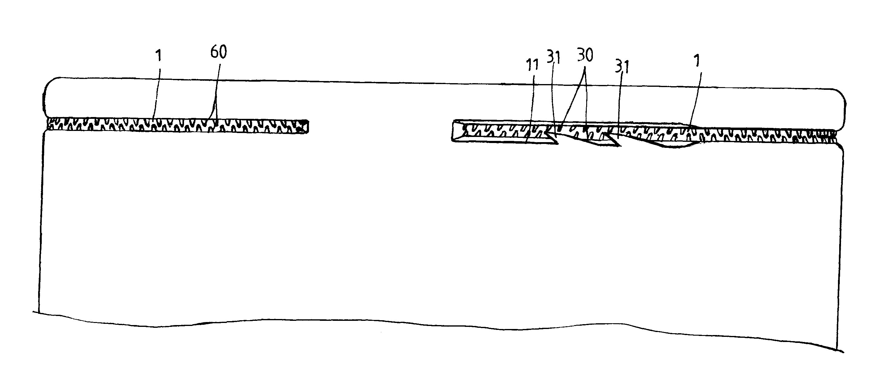
[0015]Please refer to FIGS. 5-8. As shown, the improved yarn cylinder of the invention includes a hollow cylindrical body. A groove 1 is almost annularly disposed around the cylindrical body. The groove 1 is of a C-shape and formed with four sections of teeth 30, 40, 50, 60 to define four segments 3, 4, 5, 6. A plurality of recesses 31 are formed beside the groove 1 one by one. Each recess 31 has a tapered end and a guiding slant 11, and all tapered ends are toward the same direction. This arrangement allows yarn (a) to easily enter the groove 1 and can firmly hold the yarn (a).

[0016]Please refer to FIG. 7. The yarn (a) can be easily wound in the groove 1 through the guiding slants 11 of recesses 31. The yarn (a) cannot escape from the groove 1 because the four sections of teeth 30, 40, 50, 60 in the four segments 3, 4, 5, 6 and the recesses 31 compose an interlaced holder. By the arrangement of the invention, the yarn (a) can be easily guided into the groove 1 but the yarn (a) is h...


PUM


Abstract

The yarn cylinder includes a hollow cylindrical body; a groove, almost annularly disposed around the cylindrical body, being formed with four sections of teeth to define four segments; and a plurality of recesses, located beside the groove one by one, each recess having a tapered end, and all tapered ends being toward the same direction.

Description

BACKGROUND OF THE INVENTION[0001]1. Technical Field The invention relates to filatures.[0002]2. Related Art[0003]Please refer to FIGS. 1-4, which show a typical yarn cylinder. The yarn cylinder is made of plastic and is formed with a groove 1. The groove 1 is of a C-shape with about 350 degrees. Two ends of the groove 1 are separately formed with two guiding slants 11. The groove 1 is formed with four sections of teeth 30, 40, 50, 60 to define four segments 3, 4, 5, 6. Directions of two adjacent sections of teeth 30, 40, 50, 60 are different from each other.[0004]A division line 300, 400, 500, 600 is defined between every two adjacent sections of teeth 30, 40, 50, 60. Directions of two adjacent sections of teeth 30, 40, 50, 60 meet at an angle. However, the groove 1 with the guiding slants 11 is too narrow, so yarn is not easy to enter the groove 1. And the guiding slants 11 do not have enough holding ability.SUMMARY OF THE INVENTION[0005]An object of the invention is to provide an ...

Claims


Application Information

Patent Timeline
IPC IPC(8): D04B35/00
CPCB65H75/28B65H65/00B65H75/10B65H2701/31B65H2701/5122
Inventor LIN, YING-LING
Owner LIN YING LING
Why Eureka
Try Eureka