Direct observation event triggering of drowsiness

a technology of drowsiness and observation event, which is applied in the direction of instruments, vehicle components, propulsion unit safety devices, etc., can solve the problem of difficult detection of such behavior from raw sensor data

Active Publication Date: 2014-07-31
DRIVECAM
View PDF2 Cites 135 Cited by
  • Summary
  • Abstract
  • Description
  • Claims
  • Application Information

AI Technical Summary

Problems solved by technology

Detecting such behavior from the raw sensor data can be very difficult.

Method used


Image

  • Direct observation event triggering of drowsiness
  • Direct observation event triggering of drowsiness
  • Direct observation event triggering of drowsiness

Examples


Embodiment Construction

[0022]The invention can be implemented in numerous ways, including as a process; an apparatus; a system; a composition of matter; a computer program product embodied on a computer readable storage medium; and / or a processor, such as a processor configured to execute instructions stored on and / or provided by a memory coupled to the processor. In this specification, these implementations, or any other form that the invention may take, may be referred to as techniques. In general, the order of the steps of disclosed processes may be altered within the scope of the invention. Unless stated otherwise, a component such as a processor or a memory described as being configured to perform a task may be implemented as a general component that is temporarily configured to perform the task at a given time or a specific component that is manufactured to perform the task. As used herein, the term ‘processor’ refers to one or more devices, circuits, and / or processing cores configured to process da...


PUM


Abstract

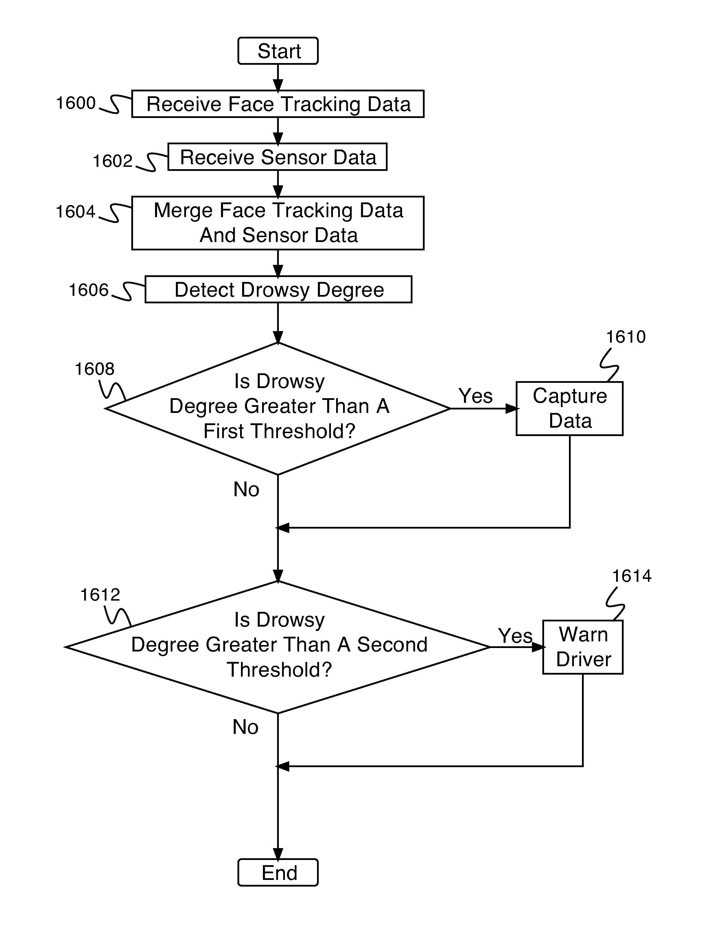
A system for event triggering comprises an interface and a processor. An interface configured to receive a face tracking data and receive a sensor data. The processor configured to determine a degree of drowsiness based at least in part on the face tracking data and the sensor data; in the event that the degree of drowsiness is greater than a first threshold, capture data; and in the event that the degree of drowsiness is greater than a second threshold, provide a warning.

Description

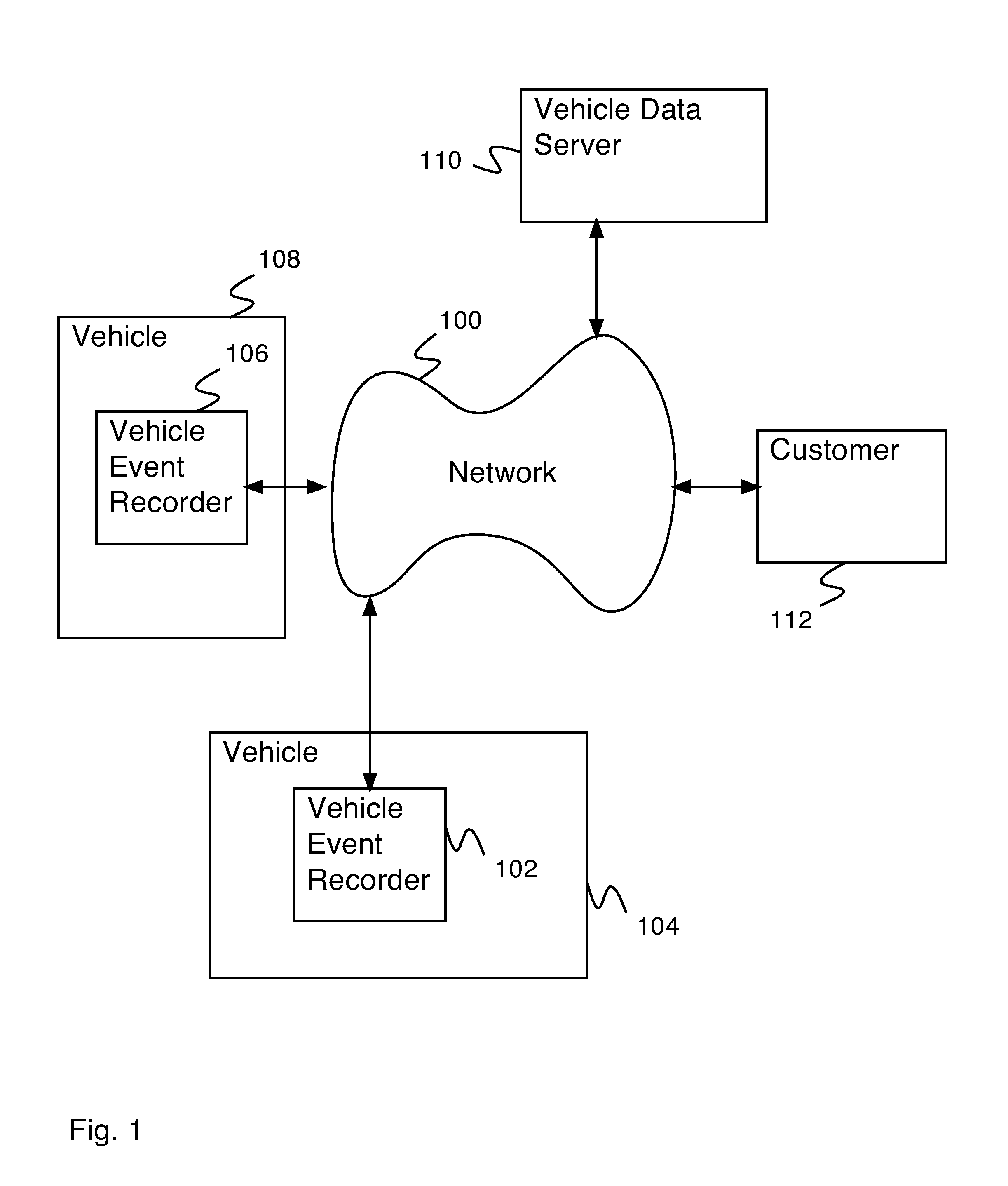
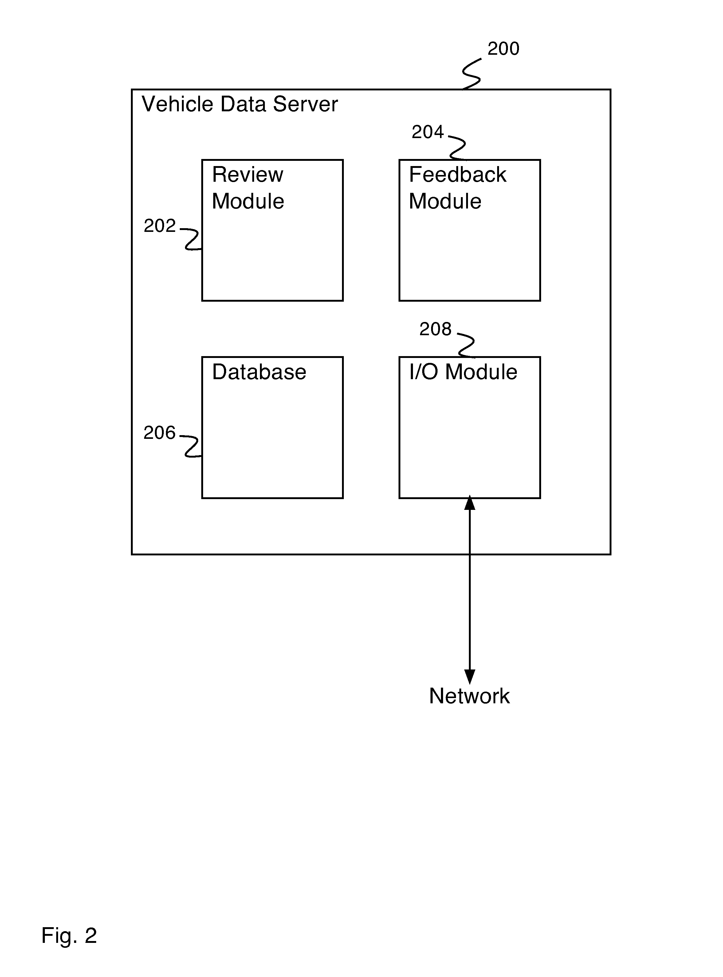
BACKGROUND OF THE INVENTION[0001]Modern vehicles (e.g., airplanes, boats, trains, cars, trucks, etc.) commonly include a vehicle event recorder in order to better understand the timeline of an anomalous event (e.g., an accident). A vehicle event recorder typically includes a set of sensors—for example, video recorders, audio recorders, accelerometers, gyroscopes, vehicle state sensors, GPS (global positioning system), etc.—that report data, which is used to determine the occurrence of an anomalous event, and which is stored for later review of the event. More advanced systems, in addition to detecting anomalous events, attempt to detect risky operator behavior—for example, behavior that is likely to lead to an anomalous event. Detecting such behavior from the raw sensor data can be very difficult.BRIEF DESCRIPTION OF THE DRAWINGS[0002]Various embodiments of the invention are disclosed in the following detailed description and the accompanying drawings.[0003]FIG. 1 is a block diagram...

Claims


Application Information

Patent Timeline
Patent Type & Authority Applications(United States)
IPC IPC(8): G08B21/06
CPCG08B21/06B60K28/066
Inventor NEMAT-NASSER, SYRUS C.
Owner DRIVECAM
Why Eureka
Try Eureka