
Radio Bearer Dependent Forwarding for Handover

a radio bearer and handover technology, applied in the field of wireless communication, can solve the problem of short handover latency at the expense of data traffic between nodes, and achieve the effect of short handover latency, and reduced x2 interface traffi

Active Publication Date: 2014-07-31
GUANGDONG OPPO MOBILE TELECOMM CORP LTD
View PDF3 Cites 0 Cited by
  • Summary
  • Abstract
  • Description
  • Claims
  • Application Information

AI Technical Summary

Benefits of technology

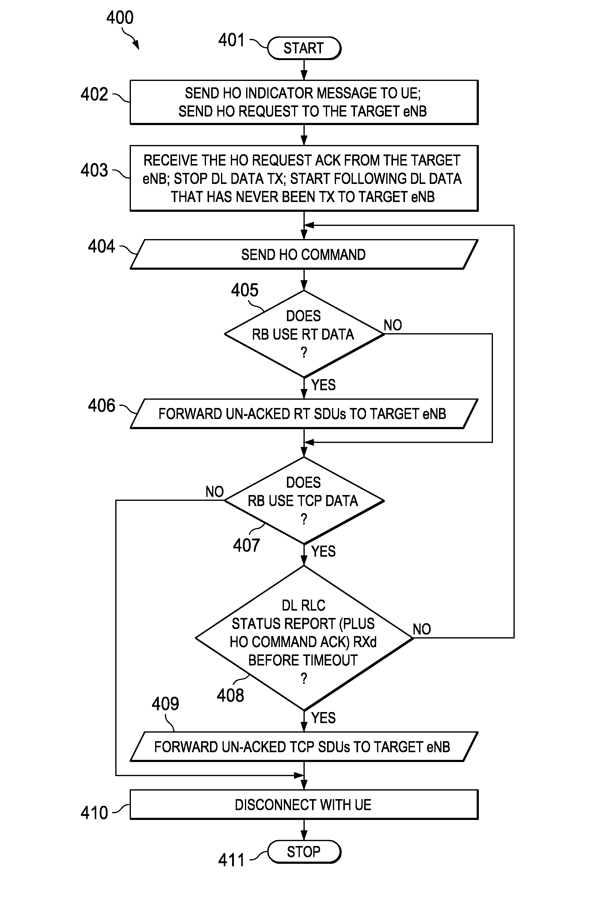
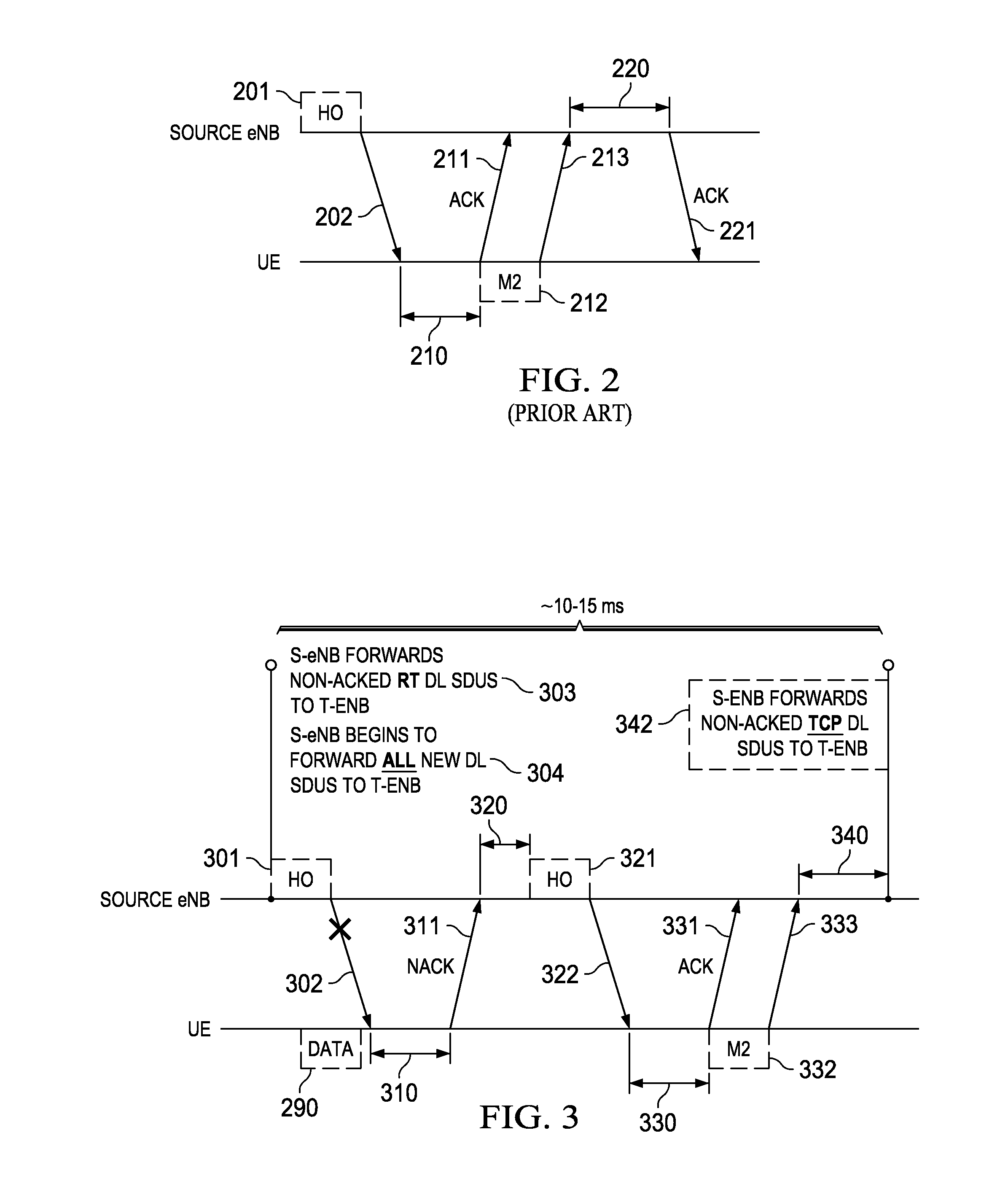
This patent describes a method for optimizing the hand-off of data between base stations in a wireless network. The method takes into account the quality of service requirements of the data flows currently existing in user equipment. For real-time data, the method reduces hand-off latency by disconnecting the source node from the data while still receiving acknowledgements from the user equipment. However, for data that does not need real-time delivery, such as transmission control protocol data, the method increases hand-off latency by continuing to receive acknowledgements and reducing X2 interface traffic between the source and target nodes. Overall, this method improves the efficiency and reliability of wireless network data handling.

Problems solved by technology

This makes the handoff latency short at the expense of data traffic between nodes.

Method used


Image

  • Radio Bearer Dependent Forwarding for Handover
  • Radio Bearer Dependent Forwarding for Handover
  • Radio Bearer Dependent Forwarding for Handover

Examples


Embodiment Construction

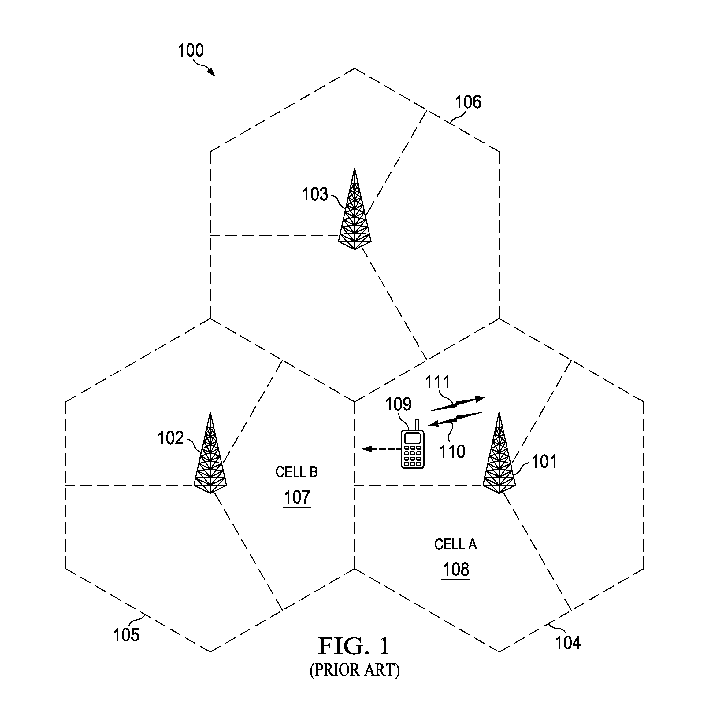
[0010]FIG. 1 shows an exemplary wireless telecommunications network 100. The illustrative telecommunications network includes base stations 101, 102 and 103, though in operation, a telecommunications network necessarily includes many more base stations. Each of base stations 101, 102 and 103 are operable over corresponding coverage areas 104, 105 and 106. Each base station's coverage area is further divided into cells. In the illustrated network, each base station's coverage area is divided into three cells. Handset or other user equipment (UE) 109 is shown in Cell A 108. Cell A 108 is within coverage area 104 of base station 101. Base station 101 transmits to and receives transmissions from UE 109. As UE 109 moves out of Cell A 108 and into Cell B 107, UE 109 may be handed over to base station 102. Because UE 109 is synchronized with base station 101, UE 109 can employ non-synchronized random access to initiate handover to base station 102.

[0011]Non-synchronized UE 109 also employs...


PUM


Abstract

This invention employs an inherent tradeoff in a radio bearer dependent data handling method for intra-E-UTRA handoffs. For user equipment using real time data, the source node forwards to the target node not yet acknowledged real time service data units and disconnects. This makes the handoff latency short at the expense of data traffic between nodes. For user equipment not needing real time data, the source node continues to receive user equipment acknowledgements during a time out period and only forwards service data units acknowledged during the time out period. This reduces X2 interface traffic between the source and target nodes but extends the handoff latency.

Description

CLAIM OF PRIORITY[0001]This application claims priority under 35 U.S.C. 119(e) (1) to U.S. Provisional Application No. 60 / 944,914 filed Jun. 19, 2007, which is incorporated by reference. This application is a continuation of and claims priority from U.S. application Ser. No. 12 / 141,439, filed Jun. 18, 2008, which is incorporated by reference.TECHNICAL FIELD OF THE INVENTION[0002]The technical field of this invention is wireless communication.BACKGROUND OF THE INVENTION[0003]An emerging wireless communication standard Evolved Universal Terrestrial Radio Access Network (E-UTRAN) has determined that during handover (HO) of user equipment (UE) from one base station (E-UTRAN node B or eNB) to another, the source eNB forwards all packet data convergence protocol (PDCP) service data units (SDU) corresponding to the unacknowledged radio link control (RLC) protocol data units (PDU). It has not yet been determined whether the final RLC status report is forwarded to the source eNB or the targe...

Claims


Application Information

Patent Timeline
Patent Type & Authority Applications(United States)
IPC IPC(8): H04W36/24
CPCH04W36/24H04W36/02H04W36/249
Inventor VEDANTHAM, RAMANUJABHADRA, SANDEEPKANGUDE, SHANTANUBAEK, SEUNG
Owner GUANGDONG OPPO MOBILE TELECOMM CORP LTD
Learn More