Park brake actuator

a technology for park brakes and actuators, which is applied in the direction of brake systems, mechanical devices, transportation and packaging, etc., can solve the problems of user or driver undesirably, load variation is likewise undesirably experienced by the operator of the vehicle, and the force required to shift the vehicle into the park to vary, so as to prevent severe ratcheting forces

Active Publication Date: 2014-08-07
FORD GLOBAL TECH LLC
View PDF4 Cites 25 Cited by
  • Summary
  • Abstract
  • Description
  • Claims
  • Application Information

AI Technical Summary

Benefits of technology

[0012]The springs are separated by a fluid damper to prevent severe ratcheting forces from accidentally actuating the flat tow / neutral state.

Problems solved by technology

The resulting inconsistency of spring compression causes the force required to shift the vehicle into park to vary from shift to shift.
Because the shifter is mechanically coupled to the park rod in these prior systems, the user or driver of the vehicle undesirably “feels” or experiences inconsistent or different forces at the shifter when shifting the vehicle into park.
This load variation is likewise undesirably experienced by an operator of the vehicle.
Another drawback with these prior mechanical systems occurs when a driver inadvertently shifts into park while the vehicle is still moving.
Particularly, if the vehicle is moving above a certain speed, the parking pawl may not fully engage the park gear, but rather “ratchets” against the gear, thereby creating an unaesthetic sound and vibration and potentially damaging the parking pawl and park gear.
Moreover, when residual torque remains within the output shaft during a parking event (e.g., when the vehicle is parked on an inclined or declined surface), the park gear imparts a torsional force or load on the parking pawl which may be transmitted through the park rod and may result in undesirable vibrations which can be “felt” or experienced at the vehicle's shifter.
Vehicles which utilize a “shift by wire” system, where the shifter is mechanically coupled to and actuates the park rod by use of a wire or cable, suffer from other drawbacks.
By way of example and without limitation, the cable may act as a noise and / or vibration path or medium which generates undesirable noise and / or vibration that can be experienced within the passenger compartment.

Method used


Image

  • Park brake actuator
  • Park brake actuator
  • Park brake actuator

Examples


Embodiment Construction

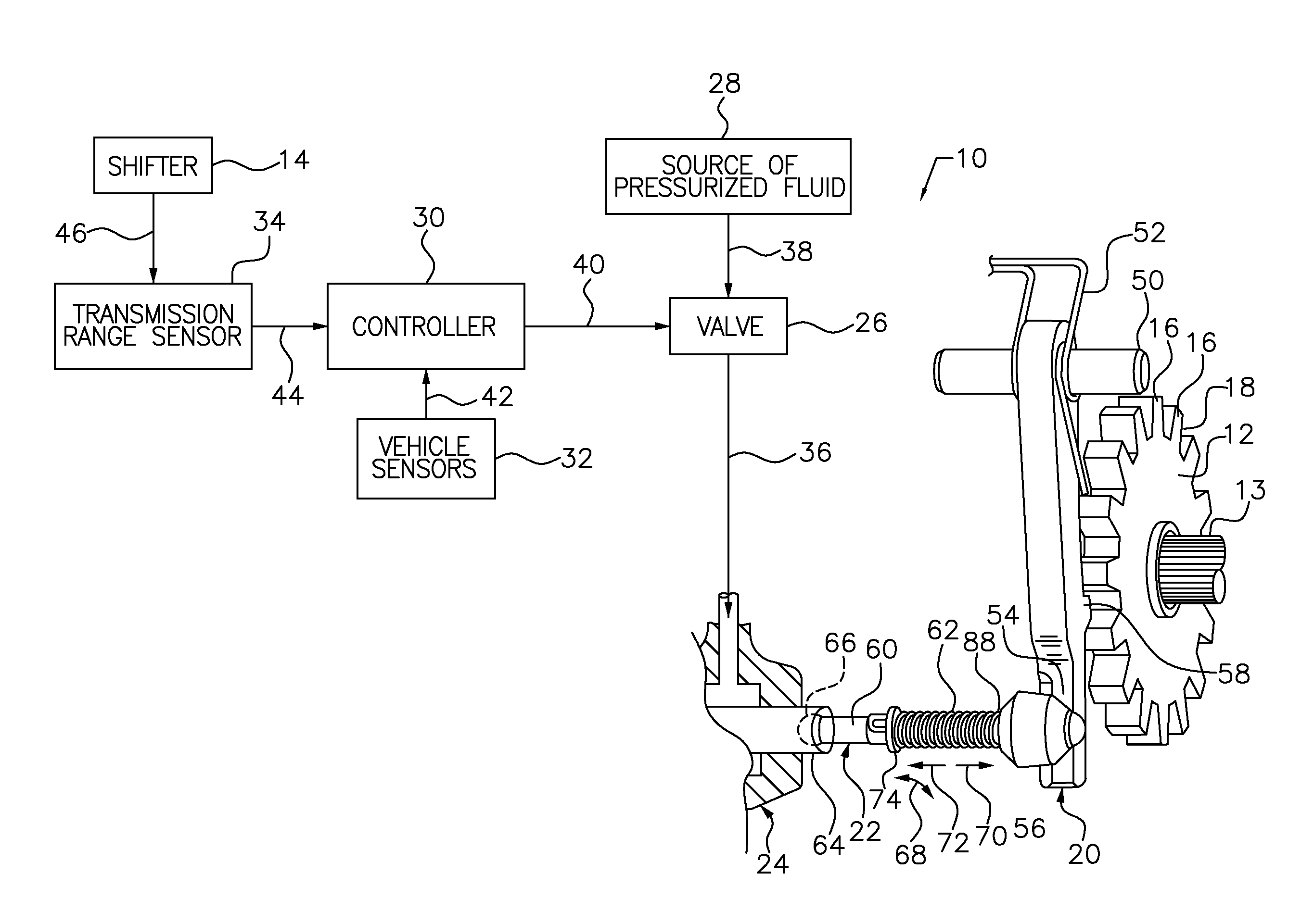
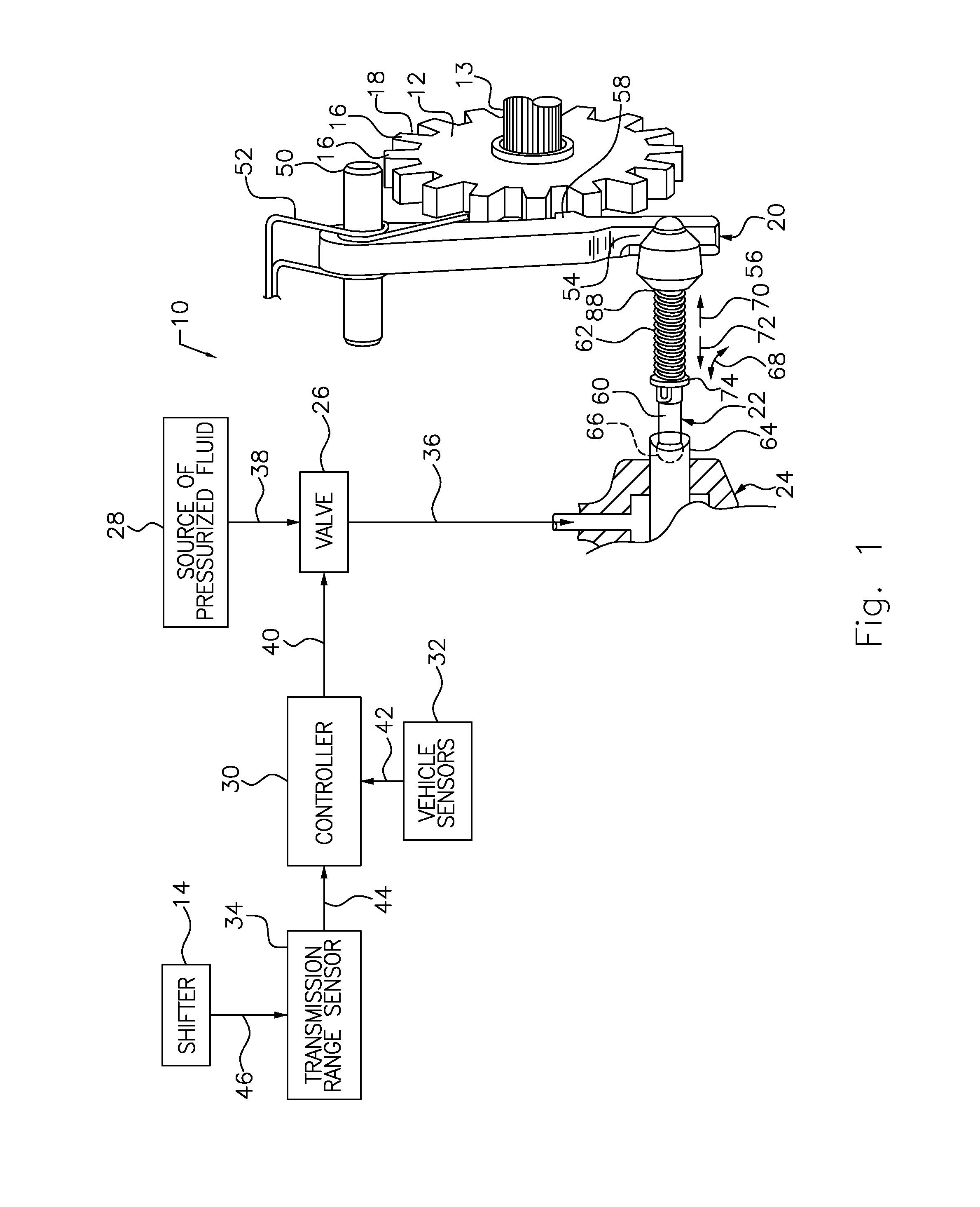
[0019]The parking assembly 10 shown in FIG. 1 is adapted for use in combination with a vehicle having a park gear 12 and a shifter 14, by which the operating range of an automatic transmission is selected manually.

[0020]Park gear 12 is secured to the vehicle's transmission output shaft 13 and rotates with the output shaft 13. Park gear 12 includes several peripherally disposed and substantially identical teeth or projections 16, each tooth 16 being separated from an adjacent tooth by a recess portion 18. When the parking pawl 20 engages the park gear 12 by entering one of the recesses, thereby substantially preventing the park gear 12 and output shaft 13 from rotating.

[0021]The shifter 14 is movable among several positions, such as a “park” position, “reverse” position, “neutral” position, and “drive” position (P R N D), which respectively correspond to various operating states of the transmission. The operating states may be selected by moving a shifter lever or by a push-buttons.

[...


PUM


Abstract

A park-brake actuator includes a cam including first serrations and an open-ended slot, a piston including second serrations displaceable relative to the cam in response to variable pressure applied to the piston, a spring, and a rod including a pin urged by the spring toward the slot and contact with the first and second serrations, the pin moved by piston displacement from the slot, onto one of the first serrations to a flat-tow position.

Description

BACKGROUND OF THE INVENTION [0001]1. Field of the Invention[0002]This invention relates generally to actuation of a motor vehicle park brake that produces engagement, disengagement and flat-tow operation of a park brake operated by a shift-by wire system.[0003]2. Description of the Prior Art[0004]Parking mechanisms or assemblies are used in automotive vehicles to allow the vehicle to enter into and maintain a “parked” condition or state. Parking assemblies typically include a park rod, which selectively actuates a parking pawl that operatively engages the vehicle's park gear, thereby maintaining the vehicle in a “parked” position or state.[0005]The park rod is typically mechanically linked to the vehicle's shifter and moves in response to shifter movement. When the shifter is moved to the “park” position, a contact member, which is disposed on the park rod, engages the parking pawl, which pivots or rotates into a position where it is disposed between a pair of teeth on the park gear...

Claims


Application Information

Patent Timeline
Patent Type & Authority Applications(United States)
IPC IPC(8): B60T11/04
CPCB60T11/04B60T1/005B60T1/062F16D63/006F16D2121/04F16D2125/66F16H63/3458F16H63/3483F16H63/3425F16H63/483
Inventor HEUVER, BRADLEY R.
Owner FORD GLOBAL TECH LLC
Why Eureka
Try Eureka