Pressure feed flow battery system and method

a flow battery and flow system technology, applied in the direction of electrolyte stream management, indirect fuel cells, electrochemical generators, etc., can solve the problems of reducing the overall efficiency of the flow battery, pressure spikes, and reducing the productive life of the flow battery

Inactive Publication Date: 2014-08-07
ASHLAWN ENERGY
View PDF0 Cites 24 Cited by
  • Summary
  • Abstract
  • Description
  • Claims
  • Application Information

AI Technical Summary

Problems solved by technology

Generally the pumps are electric powered and consume part of the flow battery's source of electricity, thus reducing the flow battery's over-all efficiency.
Accordingly, having the pumps located between the storage tanks and the battery stack introduces pump induced fluttering in the fluid flow, pressure spikes when the pumps are turned on and off, pump-induced pressure differentials across the battery stack membranes, and pump induced turbulence in the electrolyte fluid flow.
The wet and flaccid membranes of the battery stack instantly respond to these pressure differences resulting in mechanical stress to the membranes that over time will reduce their productive life.
The turbulent flow causes increased fluid flow resistance in the battery stack(s), which in turn decreases pumping efficiency and increases pumping energy requirements.
The problem for a large battery using gravity feed is that this gravity feed flow battery approach typically requires thousands of gallons of acid in storage tanks to be placed at an elevated height, which would be both expensive and dangerous.
These storage tanks may occasionally leak due to a variety of possible causes, including containment failures and natural disasters.
Such accidental spills are made worse by above ground placement of the storage tanks, where leaking electrolyte acid could potentially rain down on workers trying to repair the leaking components.

Method used


Image

  • Pressure feed flow battery system and method
  • Pressure feed flow battery system and method
  • Pressure feed flow battery system and method

Examples


Embodiment Construction

[0064]Reference will now be made in detail to one or more embodiments, illustrated in the accompanying drawings, wherein like reference numerals refer to like elements throughout. In this regard, embodiments of the present invention may be embodied in many different forms and should not be construed as being limited to embodiments set forth herein. Accordingly, embodiments are merely described below, by referring to the figures, to explain aspects of the present invention.

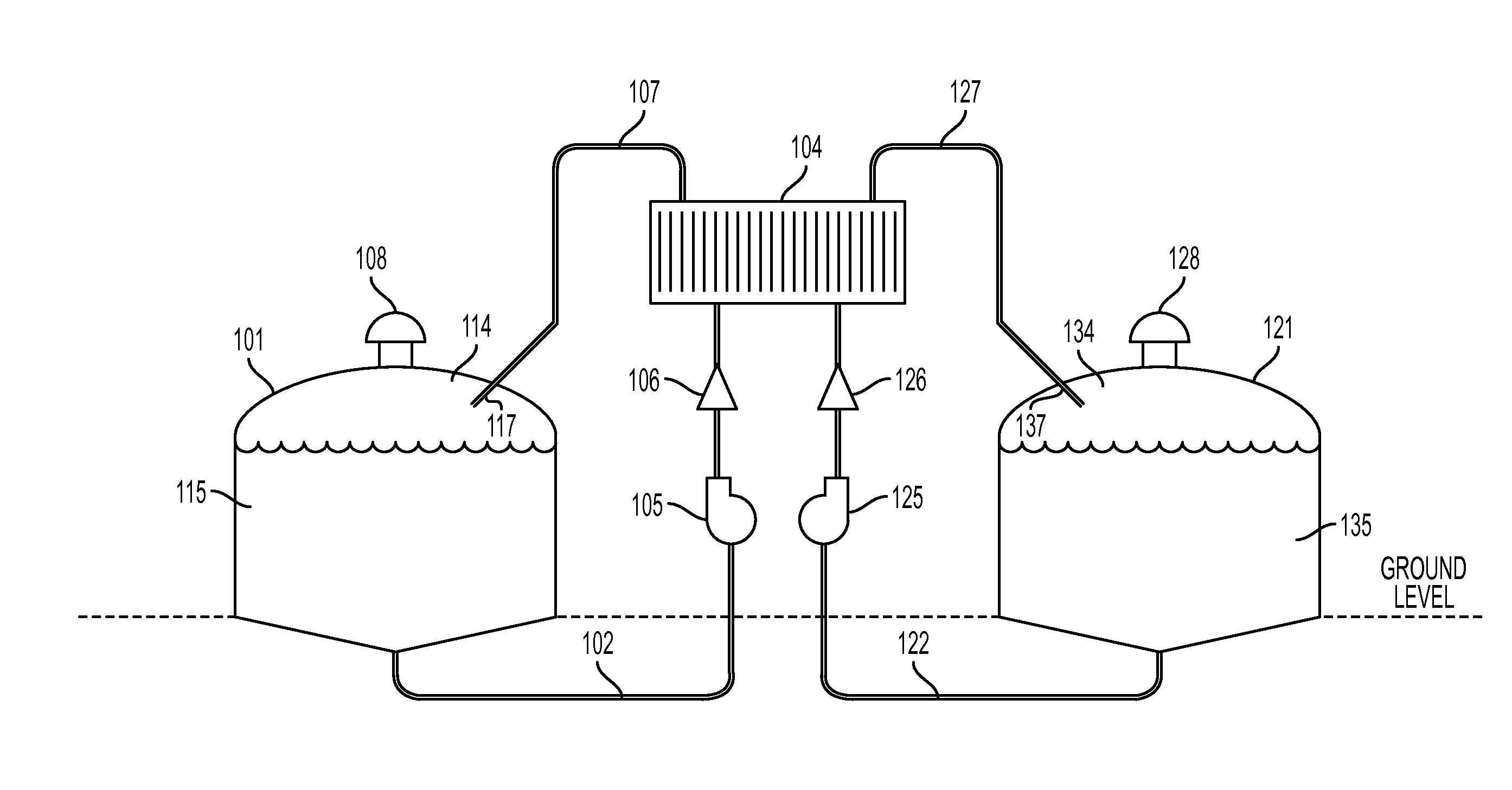
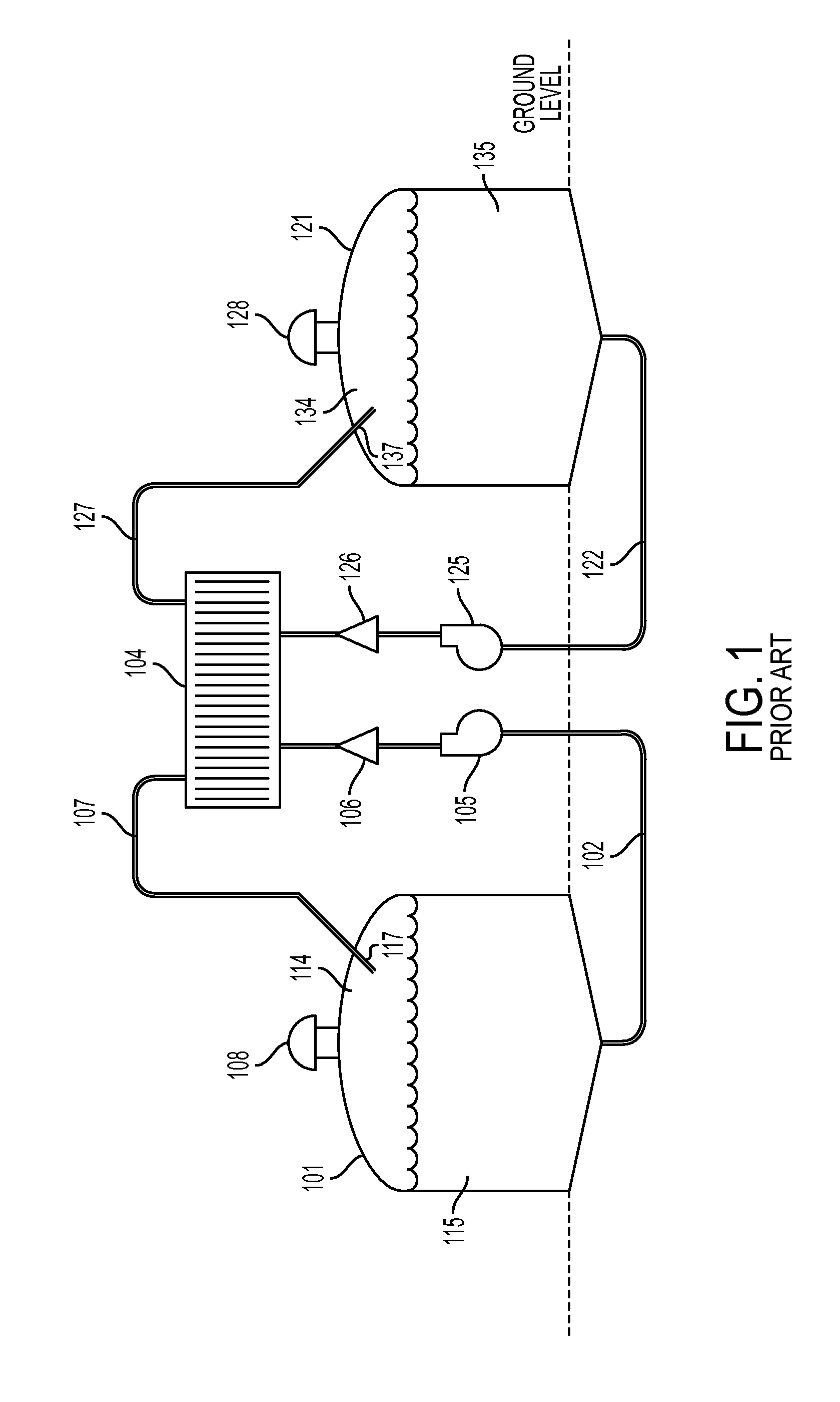
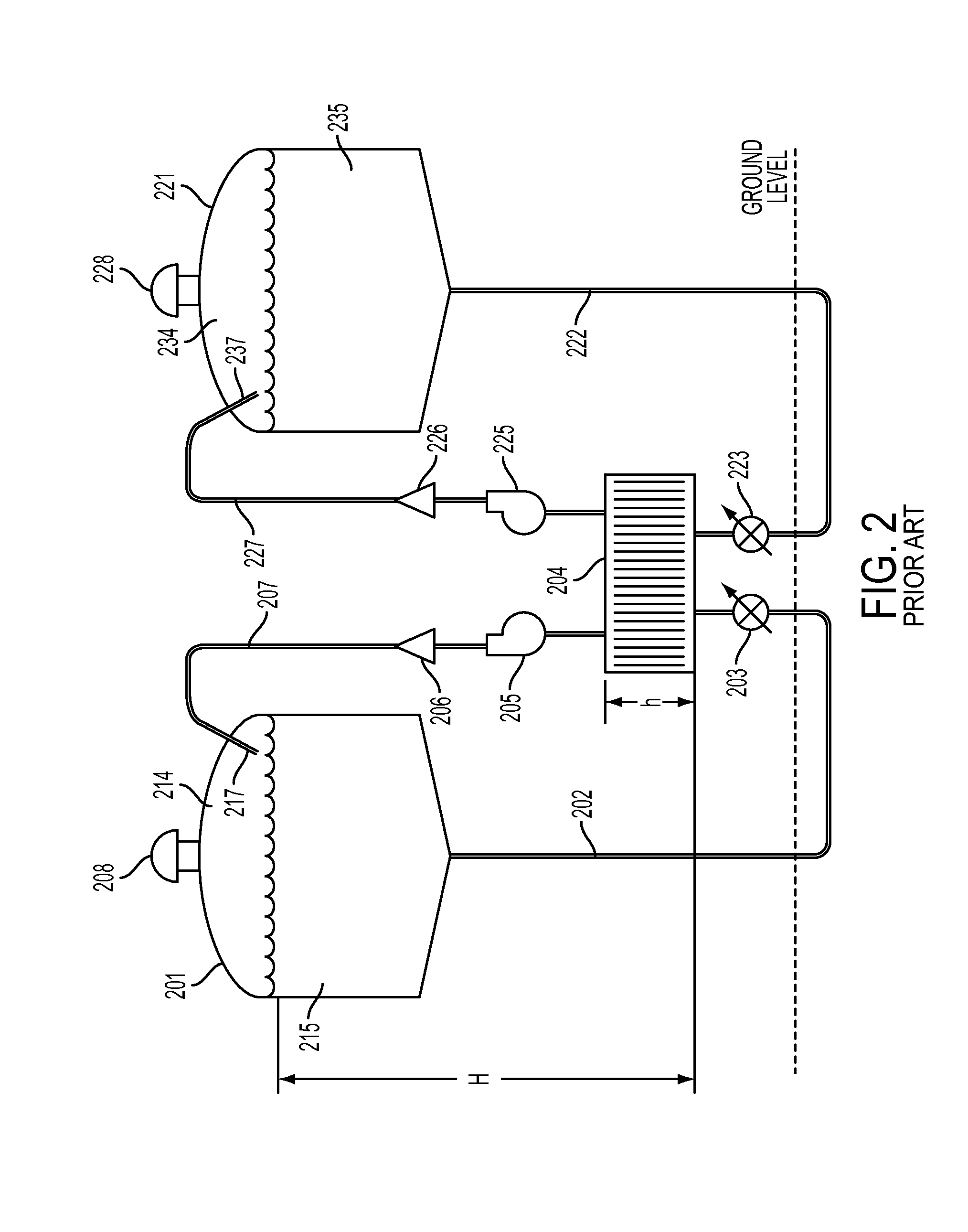
[0065]One or more embodiments relates to a method of using pressure to control the distribution of electrolytes through a battery stack portion of a redox flow battery. In one or more embodiments, such a pressure feed approach can be used to distribute electrolytes through the battery stack(s) without the need to place pumps between the electrolyte storage tanks and the battery stack(s). In one or more embodiments, several methods of using pressurized tanks to provide sufficient head pressure to push electrolyte th...


PUM

PropertyMeasurementUnit
electric poweraaaaaaaaaa
poweraaaaaaaaaa
flow rateaaaaaaaaaa

Abstract

A flow battery system and method are provided. The flow battery system includes a first battery stack including a first half-cell, a first pressure feed system, including at least a first storage tank and a first booster tank to store a liquid electrolyte, designed to generate a first booster pressure in the first booster tank sufficient to force the liquid electrolyte to be fed from the first pressure feed system through the first half-cell, and a return system to return the liquid electrolyte from the first half-cell to the first pressure feed system. The return system may include a gravity feed system returning liquid electrolyte from the first half-cell to a collection tank, and a pump to return the collected liquid electrolyte from the collection tank to the first storage tank. The pressure feed flow battery system may have a two-tank, divided 2-tank, or four-tank flow battery configurations.

Description

CROSS-REFERENCE TO RELATED APPLICATIONS[0001]This application claims the benefit of U.S. Provisional Application No. 61 / 849,706, filed Feb. 1, 2013, in the United States Patent and Trademark Office, the disclosure of which is incorporated herein by reference.BACKGROUND[0002]1. Field[0003]One or more embodiments related to a flow battery system having a pressure feed system, and more particularly, to a flow battery system having a pressure feed system that uses a booster tank to generate sufficient head pressure at a battery stack to force electrolyte through the battery stack for charging or discharging the flow battery system.[0004]2. Description of the Related Art[0005]Reduction-oxidation (redox) flow batteries, also known as regenerative fuel cells, or reversible fuel cells, or secondary fuel cells, are a type of storage battery having two liquid electrolytes; a positive electrolyte or catholyte, and a negative electrolyte or anolyte.[0006]The two electrolytes are typically separ...

Claims


Application Information

Patent Timeline
Patent Type & Authority Applications(United States)
IPC IPC(8): H01M8/04H01M8/20H01M8/18
CPCH01M8/04276H01M8/20H01M8/188H01M8/04186H01M8/04425H01M8/04604H01M8/04753Y02E60/50
Inventor DANIEL, MAURICE
Owner ASHLAWN ENERGY
Why Eureka
Try Eureka