Wave energy apparatus having a venturi shroud

a technology of wave energy apparatus and venturi shroud, which is applied in the direction of mechanical equipment, mechanical energy handling, machines/engines, etc., can solve the problems of not being able to generate much power, the device is generally not capable of operating in the deeper parts of the ocean, and the speed of the water's movement though the turbine is relatively slow

Active Publication Date: 2014-08-21
LONE GULL HLDG LTD
View PDF3 Cites 6 Cited by
  • Summary
  • Abstract
  • Description
  • Claims
  • Application Information

AI Technical Summary

Problems solved by technology

These types of devices are generally not capable of operating in the deeper parts of the ocean.
Such a device does not generate much power.
Even though the force driving the water back and forth through such a suspended turbine would be great, the speed of the water's movement though the turbine would be relatively slow.
At this speed, it would be difficult to extract a significant amount of energy from the flowing water with a simple turbine because the amount of power that can be extracted from a flowing stream of water by a turbine is proportional to the cube of its speed.
Since ocean waves rise and fall with a relatively slow speed (the maximum of which is generally only one or two meters per second), it is difficult to extract much energy from the water constrained to flow through a propeller at that same slow speed.
However, the cost of constructing and maintaining a 7-meter diameter buoy and venturi device, including a 6-meter turbine, is unacceptably high for a device with an output of only 30 kW in rather energetic 4-meter oceans.
Problems with the Heck device
The Heck device fails to generate enough power to justify its cost of construction, deployment and maintenance.
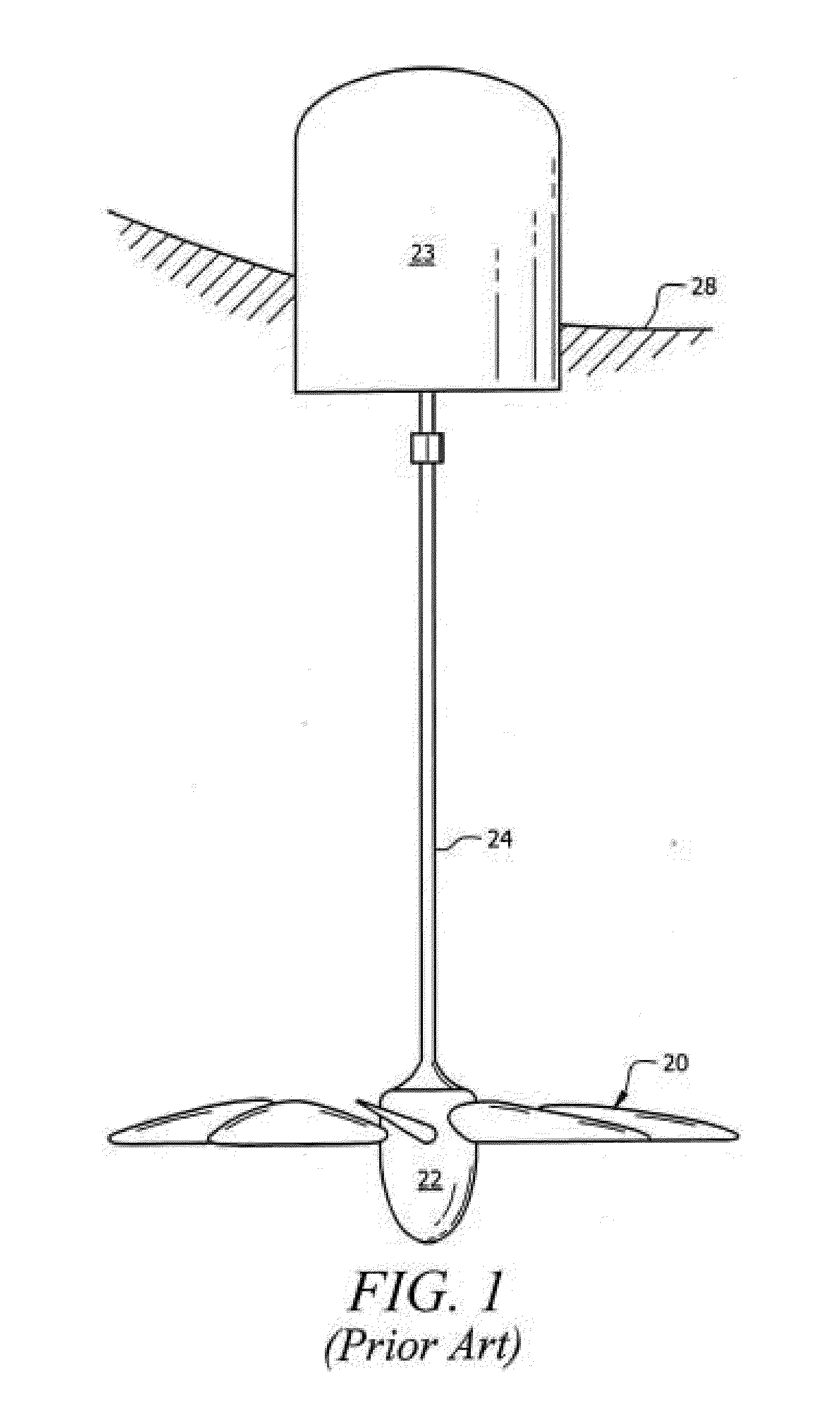
Another problem with the Heck device is its use of a single central pipe which encloses the turbine shaft and is also responsible for maintaining the attachment, and fixing the position (in a rigid manner), of the turbine and the cylindrical housing.
The stress on this single central support would be much greater than necessary and introduce serious concerns regarding the ability of the device to survive the rigors of its time at sea.

Method used


Image

  • Wave energy apparatus having a venturi shroud
  • Wave energy apparatus having a venturi shroud
  • Wave energy apparatus having a venturi shroud

Examples


Embodiment Construction

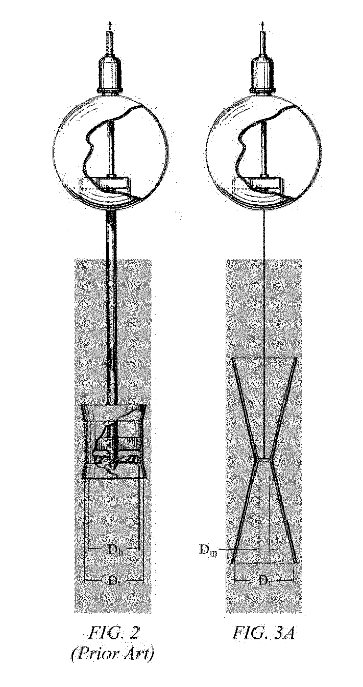
[0084]This invention provides an improved design for wave energy devices of the types proposed by Bichard and Heck, as well as an improved design for all other varieties of venturi-based wave energy devices. In addition, this invention provides a method for optimizing the design of the venturi component used in these types of devices. This optimization is made with respect to the degree to which the design's resulting venturi effect will accelerate the water flowing through the submerged component of the power-generation system, e.g. a turbine or suction device.

[0085]The preferred embodiment of this invention utilizes a venturi tube embedded within an outer cylindrical housing. The preferred embodiment of this invention rigidly connects the submerged venturi tube to the buoy above through multiple struts arranged about the periphery of the tube and the buoy. The preferred embodiment of this invention incorporates a venturi throat whose cross-sectional area is specifically designed t...


PUM


Abstract

By optimizing the degree to which water is accelerated through a venturi device, the amount of power that an energy device extracts from the ocean is maximized. Prior venturi-based wave energy devices have proven to be inefficient because of the relatively small amount of power that they generate relative to their size and cost. By optimizing the venturi effect created within the submerged venturi components of such devices, the speed of the water moving through the narrowest portions of such a devices is maximized with respect to the wave environments in which they operate, and a maximal amount of energy is extracted from the ocean. This optimization of a wave energy device's power is sufficient to render such devices cost effective. The method of extracting energy from the accelerated flow of water moving through such venturi devices is not limited, and many alternatives exist, each with its own potential benefits.

Description

RELATED APPLICATIONSCross-Reference to Related Applications[0001]This application is a continuation-in-part of U.S. patent application Ser. No. 12 / 389,928 filed Feb. 20, 2009 and also claims the benefit of the prior filing date of Provisional Patent application No. 61 / 278,327 filed Oct. 5, 2009, entitled “Venturi, Chambered Venturi and Optimized Venturi-Based Ocean Wave Energy Device” incorporated herein by reference in its entirety and the benefit of the filing date thereof is hereby claimed.BACKGROUND OF THE INVENTION[0002]1. Field of the Invention[0003]This invention relates, generally, to wave-driven energy conversion devices that convert the abundant natural energy present in the oceans and other bodies of water into electrical or chemical energy.[0004]2. Description of Prior Art[0005]2a. Overview[0006]2a1. Water Turbines[0007]Water turbines have been used to extract useful energy from moving water, or water under pressure, for thousands of years. Many different types of water ...

Claims


Application Information

Patent Timeline
Patent Type & Authority Applications(United States)
IPC IPC(8): F03B13/22
CPCF03B13/22F05B2240/242F05B2250/25Y02E10/30H02K7/1823
Inventor MOFFAT, BRIAN L.
Owner LONE GULL HLDG LTD
Why Eureka
Try Eureka