
Method of Using Star Wheel with Adjustable Directional Biaser

a technology of directional biasing and star wheel, which is applied in the field of media feed systems, can solve the problems of excessive wear of star wheel over the life of imaging device, not being able to adjust, so as to increase the biasing force of star wheel, increase the nip height, and reduce the nip height

Active Publication Date: 2014-08-21
LEXMARK INT INC
View PDF8 Cites 0 Cited by
  • Summary
  • Abstract
  • Description
  • Claims
  • Application Information

AI Technical Summary

Benefits of technology

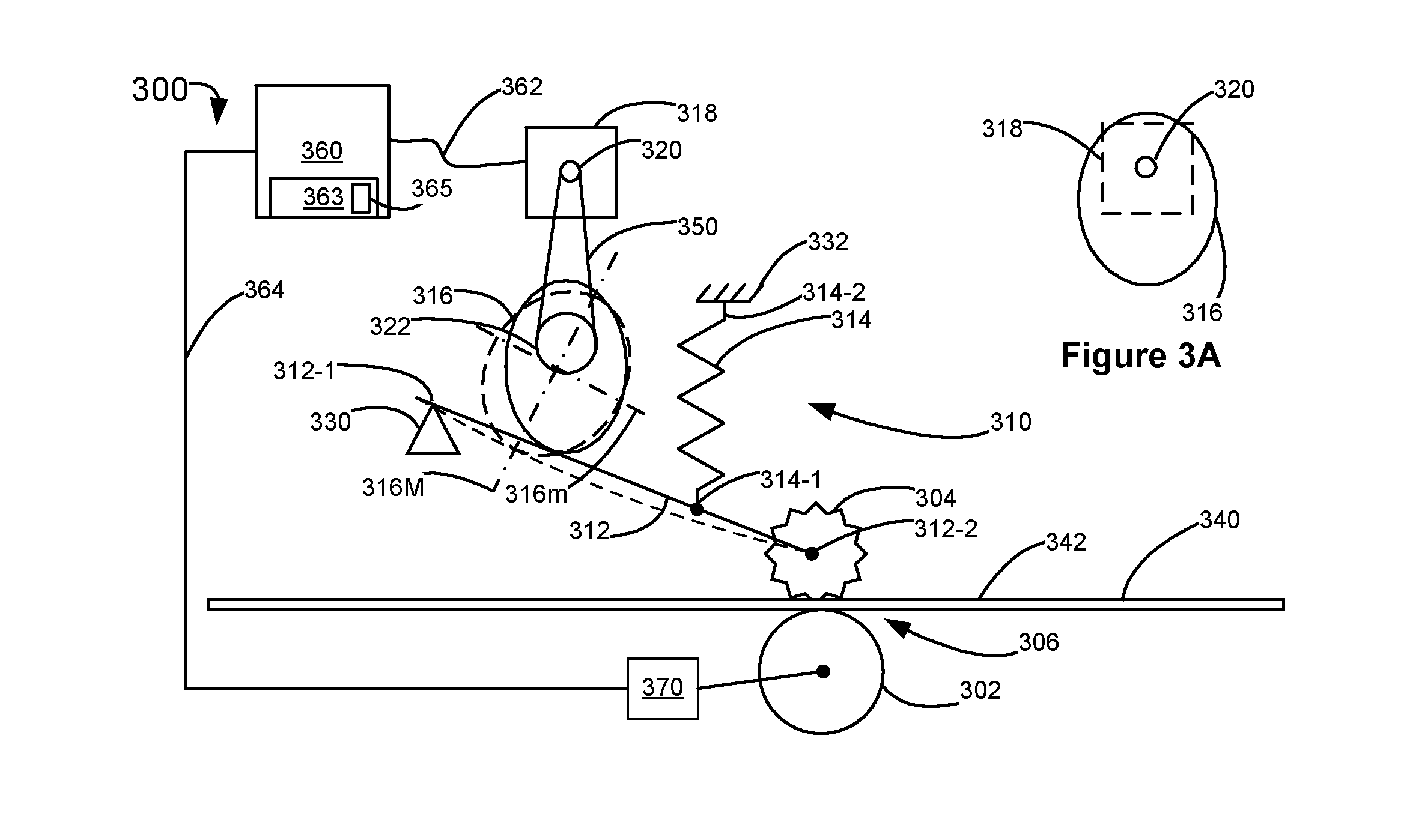
The patent text describes a method of printing with an inkjet printer that includes a printhead, a star wheel, and an adjustable biaser. The method involves analyzing print data to determine an area of printing and calculating the density of the printing in that area. The ink is then printed in that area and the printed area is advanced past the star wheel. The adjustable biaser is used to lift the star wheel off the sheet and lower it back onto the sheet after the printed area has advanced past the star wheel. This method ensures consistent and high-quality printing. The patent also describes a method of feeding media in an inkjet printer that includes the star wheel and the adjustable biaser, which can modify the biasing force and nip height to improve the performance of the printer. These methods enable safe and efficient printing process.

Problems solved by technology

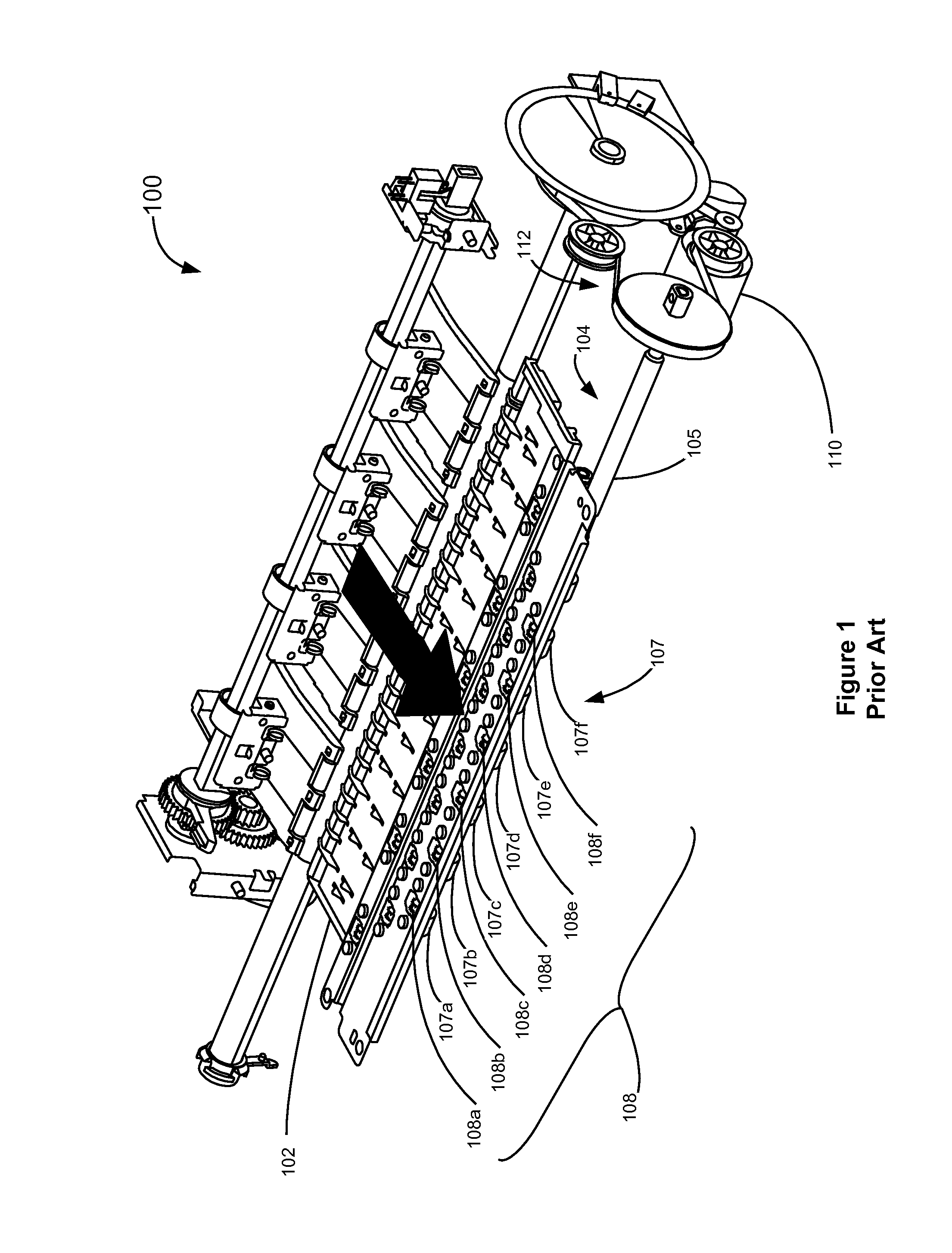
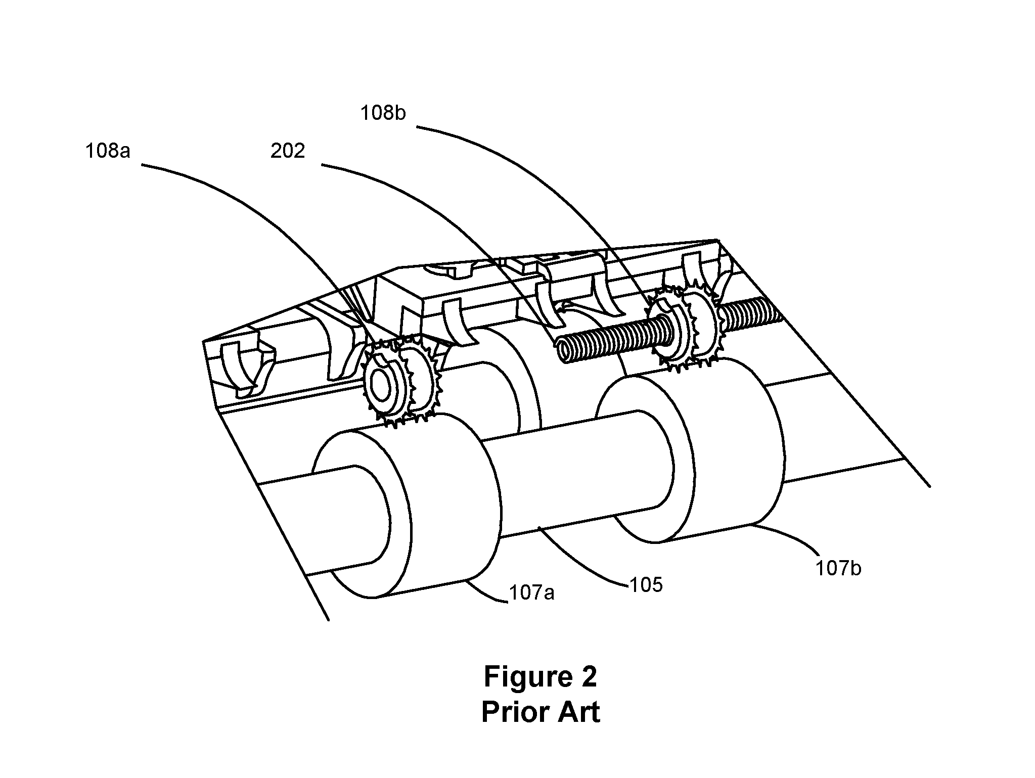
This bias is not adjustable during operation and is not adjusted to optimize the media feed system in response to, for example, different media properties.
Also, since the star wheels continuously ride on either media or on rolls, the star wheels may experience excessive wear over the life of the imaging device, especially if the roll is abrasive.
Further, the star wheels may become contaminated with ink buildup if they have excessive contact with wet ink.
Once contaminated, the star wheels may transfer ink to the media causing print defects.

Method used


Image

  • Method of Using Star Wheel with Adjustable Directional Biaser
  • Method of Using Star Wheel with Adjustable Directional Biaser
  • Method of Using Star Wheel with Adjustable Directional Biaser

Examples


Embodiment Construction

[0023]It is to be understood that the present disclosure is not limited in its application to the details of construction and the arrangement of components set forth in the following description or illustrated in the drawings. The present disclosure is capable of other embodiments and of being practiced or of being carried out in various ways. Also, it is to be understood that the phraseology and terminology used herein is for the purpose of description and should not be regarded as limiting. The use of “including,”“comprising,” or “having” and variations thereof herein is meant to encompass the items listed thereafter and equivalents thereof as well as additional items. Unless limited otherwise, the terms “connected,”“coupled,” and “mounted,” and variations thereof herein are used broadly and encompass direct and indirect connections, couplings, and mountings. In addition, the terms “connected” and “coupled” and variations thereof are not restricted to physical or mechanical connec...


PUM


Abstract

A method of printing with an inkjet printer including a printhead, a star wheel located downstream from the printhead, and an adjustable biaser coupled to the star wheel. The method comprises analyzing print data to identify an area of printing to be printed on a sheet of print media that aligns with the star wheel; calculating the density of the printing in the identified area of printing; printing the identified area of printing; determining whether the calculated density exceeds a density criteria, and if so then using the adjustable biaser to lift the star wheel off of the sheet before the printed area of printing reaches the star wheel; advancing the printed area of printing past the star wheel; and using the adjustable biaser lowering the star wheel onto the sheet after the printed area of printing has advanced past the star wheel.

Description

CROSS REFERENCES TO RELATED APPLICATIONS[0001]The present application is related to U.S. patent application Ser. No. ______, (Attorney Docket No. P89-US1) entitled “STAR WHEEL WITH ADJUSTABLE DIRECTIONAL BIASER” filed concurrently herewith and assigned to the assignee of the present application.STATEMENT REGARDING FEDERALLY SPONSORED RESEARCH OR DEVELOPMENT[0002]None.REFERENCE TO SEQUENTIAL LISTING, ETC. [0003]None.BACKGROUND[0004]1. Field of the Disclosure[0005]The present disclosure relates generally to media feed systems used in inkjet imaging devices such as printers or multifunction devices having printing capability and more particularly to a media feed system having a star wheel with adjustable bias.[0006]2. Description of the Related Art[0007]In inkjet imaging device media feed systems, it is now common practice to advance media by pinching the media between a driven media feed roll and one or more star wheels. In simplex printing, the media feed roll touches the non-printed...

Claims


Application Information

Patent Timeline
Patent Type & Authority Applications(United States)
IPC IPC(8): B41J13/00B41J13/02
CPCB41J13/025B41J13/0009
Inventor EDWARDS, MARK JOSEPHRUMFORD, ROBERT W.
Owner LEXMARK INT INC
Learn More