Optical module and electronic apparatus
a technology of optical modules and electronic devices, applied in the direction of optical radiation measurement, instruments, spectrometry/spectrophotometry/monochromators, etc., can solve the problems of interference filter distortion, interference filter distortion, and deviation in the separated wavelength or half-value width, so as to achieve high spectral accuracy
- Summary
- Abstract
- Description
- Claims
- Application Information
AI Technical Summary
Benefits of technology
Problems solved by technology
Method used
Image
Examples
first embodiment
[0049]Hereinafter, a first embodiment of the invention will be described with reference to the accompanying drawings.
1. Overall Configuration of Optical Device
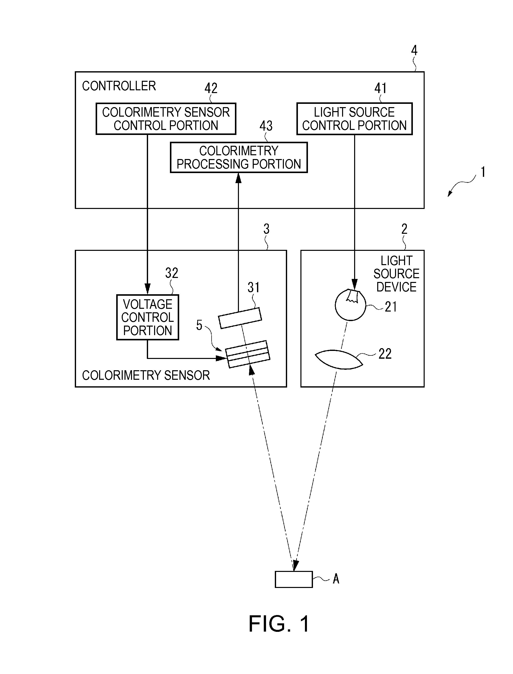
[0050]FIG. 1 is a diagram schematically illustrating a configuration of a colorimeter (electronic apparatus) according to an embodiment of the invention.
[0051]A colorimeter 1 is an electronic apparatus according to the invention, and as shown in FIG. 1, includes a light source device 2 which emits light to a measurement target A, a colorimetry sensor 3 which is an optical module according to the invention, and a controller 4 which controls an overall operation of the colorimeter 1. Further, as the measurement target A reflects light emitted from the light source device 2 and the colorimetry sensor 3 receives the reflected light to be inspected, the colorimeter 1 analyzes and measures the chromaticity of the light to be inspected, that is, the color of the measurement target A on the basis of a detection signal output from the ...
second embodiment
[0093]Next, a second embodiment of the invention will be described with reference to the accompanying drawings.
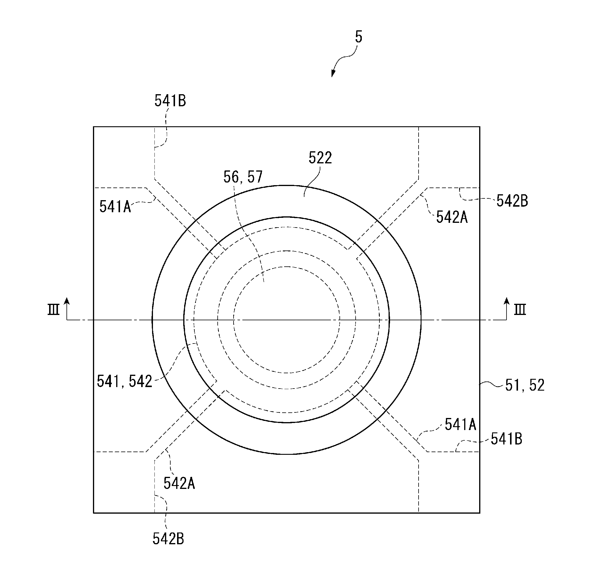
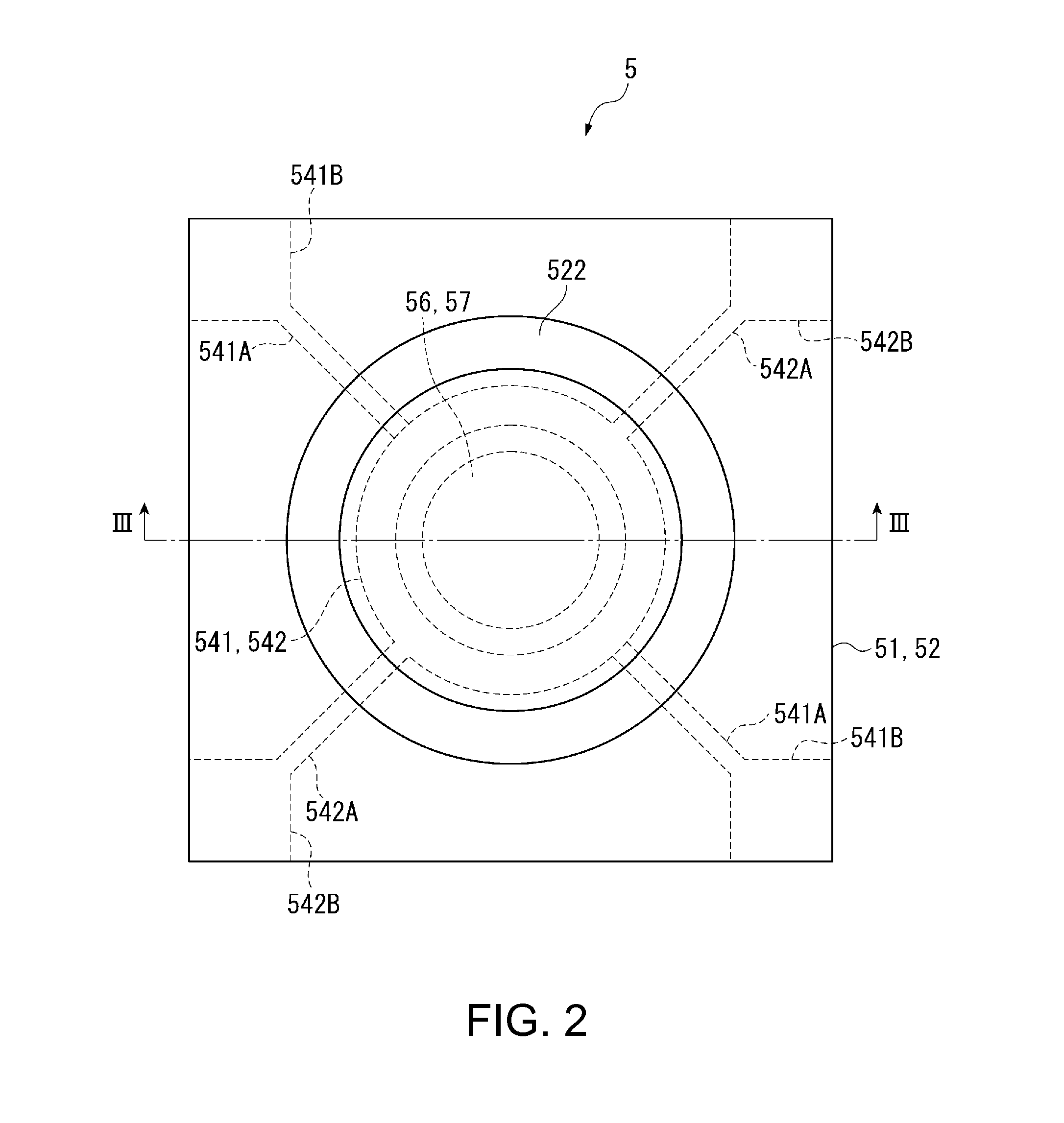
[0094]FIG. 5 is a cross-sectional view illustrating the vicinity of an interference filter 5 in a colorimetry sensor 3 (optical module) according to a second embodiment. Hereinafter, the same reference numerals are given to the same components as in the first embodiment, and its description will be omitted or simplified.
[0095]In the colorimetry sensor 3, as shown in FIG. 5, a part of the interference filter 5 is fixed to the transparent substrate 7 through a cured adhesive layer 61 obtained by curing a curable adhesive agent, and the other part of the interference filter 5 is fixed to the transparent substrate 7 through the adhesive layer 6. Further, the interference filter 5 is connected to the voltage control portion 32 by the wiring R. Further, as shown in FIG. 5, the cured adhesive layer 61 is disposed in apart (one location) of a region which overlaps with a first elec...
third embodiment
[0100]Next, a third embodiment of the invention will be described with reference to the accompanying drawings.
[0101]FIG. 6 is a cross-sectional view illustrating the vicinity of an interference filter 5 in a colorimetry sensor 3 (optical module) according to a third embodiment.
[0102]In the colorimetry sensor 3, as shown in FIG. 6, the interference filter 5 is fixed to the light receiving device 31 through the adhesive layer 6, and the light receiving device 31 is fixed to a support substrate 71 through the cured adhesive layer 61. Further, the interference filter 5 is connected to the voltage control portion 32 by the wiring R. The light receiving device 31 is connected to the colorimetry processing portion 43 by the wiring R. Further, the adhesive layer 6 is disposed in the light transmission region G and a region which overlaps with the light receiving device 31 when seen from a plan view.
[0103]Here, as the support substrate 71, the transparent substrate 7 may be used, but since t...
PUM
 Abstract
Description
Claims
Application Information
 - R&D
- Intellectual Property
- Life Sciences
- Materials
- Tech Scout
- Unparalleled Data Quality
- Higher Quality Content
- 60% Fewer Hallucinations
Browse by: Latest US Patents, China's latest patents, Technical Efficacy Thesaurus, Application Domain, Technology Topic, Popular Technical Reports.
© 2025 PatSnap. All rights reserved.Legal|Privacy policy|Modern Slavery Act Transparency Statement|Sitemap|About US| Contact US: help@patsnap.com


