
Continuous miner mid-conveyor drive

Inactive Publication Date: 2014-08-28
JOY GLOBAL UNDERGROUND MINING LLC
View PDF2 Cites 22 Cited by
  • Summary
  • Abstract
  • Description
  • Claims
  • Application Information

AI Technical Summary

Benefits of technology

The patent describes two types of continuous miners, which are machines used to cut and move rock. The first type has a mining portion and a support frame, while the second type has a cutting head boom and a loading pan. Both types have a conveyor that moves mined material from the mining portion to the discharge portion, which is designed to swing laterally. The conveyor is driven by a conveyor drive system located on a bottom surface of the continuous miner. The technical effects of the invention include improved mining efficiency, reduced damage to the rock, and easier handling and maintenance of the continuous miner.

Problems solved by technology

Often this area of bunching is only a few millimeters below centrifugal loading arms at the mining portion, creating a high likelihood of collision between the conveyor chain and the loading arms.
It has been found that collisions between a conveyor chain and centrifugal loading arms often occur even with a properly tensioned conveyor chain and empty conveyor.
Thus, with a full conveyor (i.e. one loaded with mined material), and a front drive system, collisions are more prevalent and inflict more damage.
When a chain flight bar crosses the gap and strikes the rearmost edge of the support frame, it does so with a severe impact, further stressing the chain and creating undesired high levels of noise.
However, there are disadvantages to the rear drive system.
For example, the height required for a rear drive system is generally unavailable for many continuous miners, since the very rear portion of the continuous miner must fit above the height of a shuttle car (or other vehicle) that receives the mined material off the rear of the continuous miner.
Thus, rear drive assemblies are only viable for the largest of the continuous miners.
Additionally, the rear drive assemblies run continuously in a stream of coal, ore, rock, or other mined material, which tends to pack between the rear drive sprockets and the conveyor chains, creating the potential for machine malfunction or slowing.
Additionally, the weight of the rear sprocket drive at the very rear of the continuous miner stresses the pivot location where the discharge portion of the continuous miner swings, creating the potential for damage and / or malfunction.

Method used


Image

  • Continuous miner mid-conveyor drive
  • Continuous miner mid-conveyor drive
  • Continuous miner mid-conveyor drive

Examples


Embodiment Construction

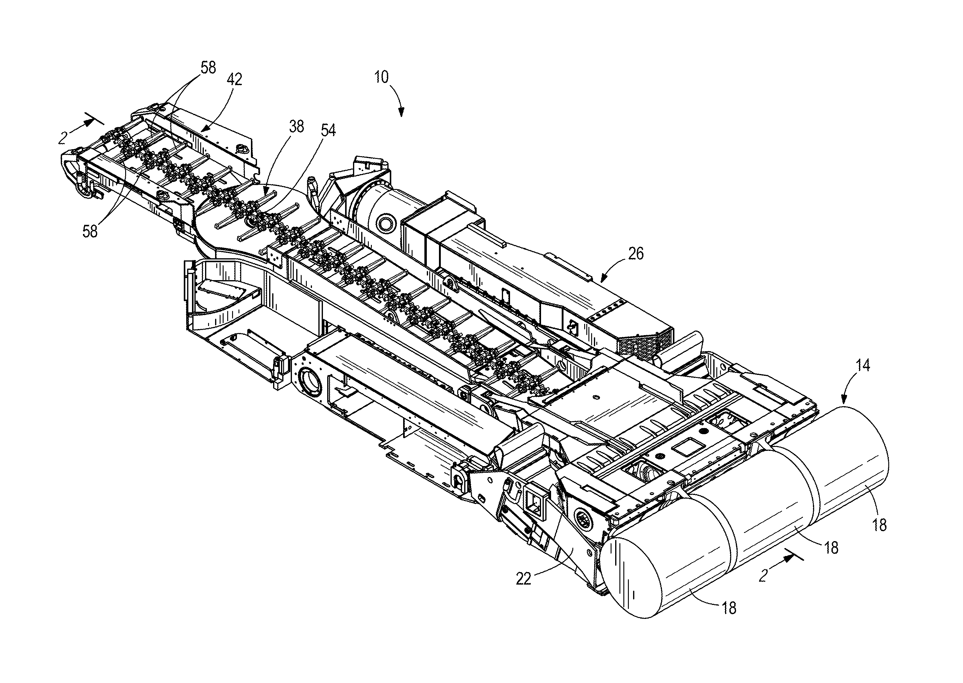
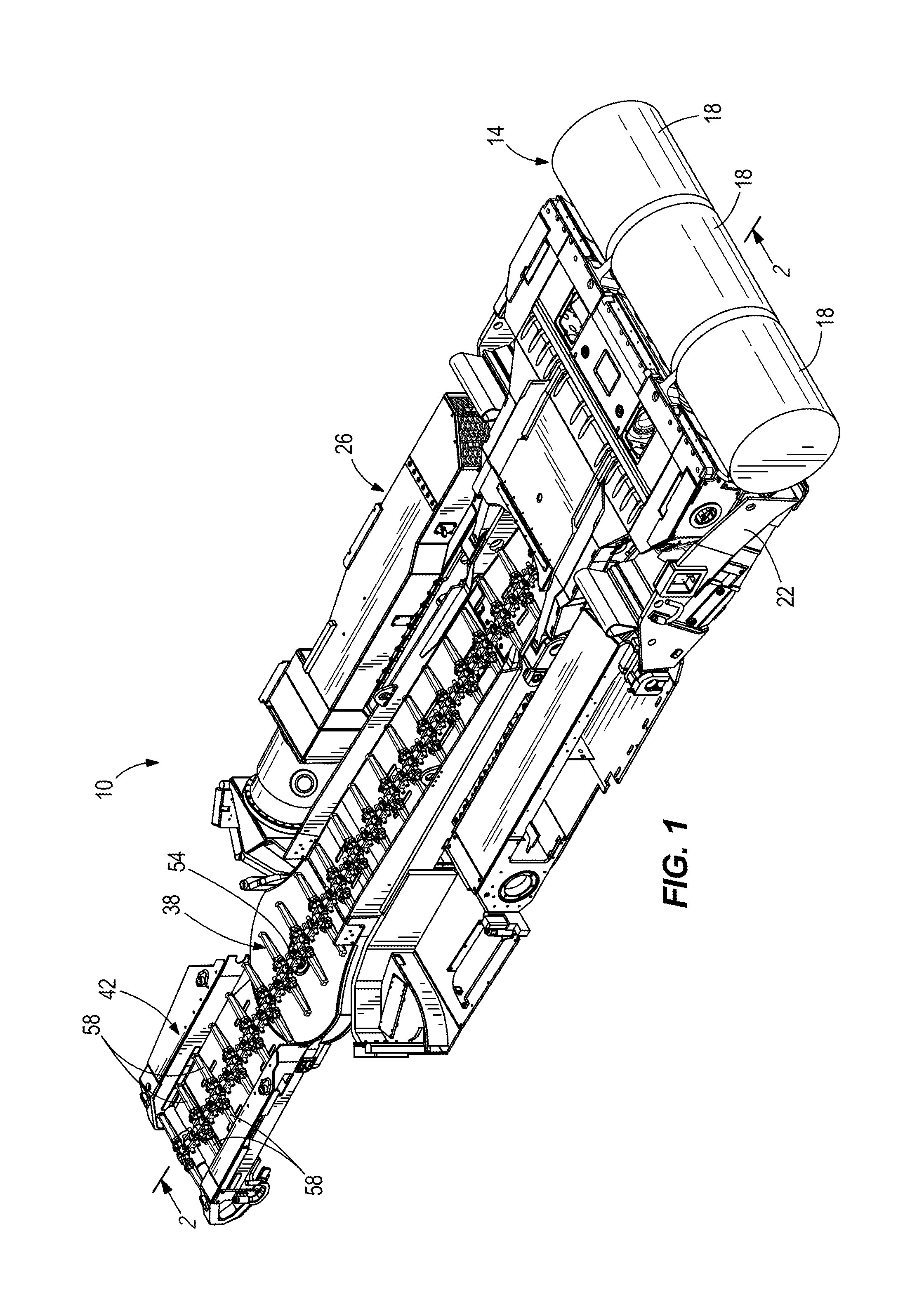
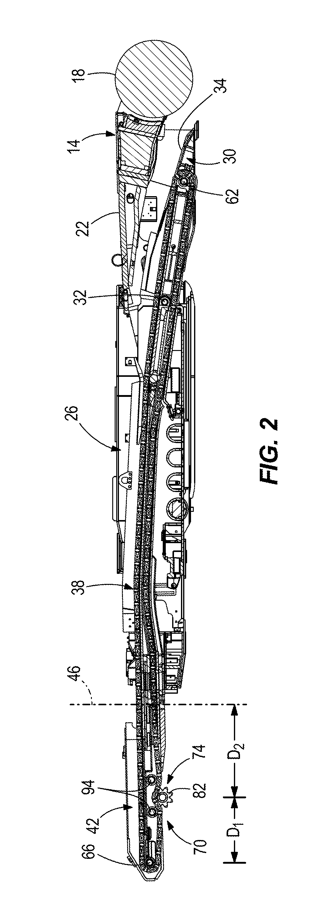
[0015]FIG. 1 is a top perspective view of a continuous miner 10. The continuous miner 10 includes a mining portion 14 used to mine material, including but not limited to coal, ore, and rock, from an underground mine. The mining portion 14 includes a plurality of rotary cutting heads 18. The rotary cutting heads 18 are used to crush, drag, cut, and / or otherwise remove material from the wall of a mine. With reference to FIG. 2, the rotary cutting heads 18 rotate clockwise, so as to direct material in a downward, and rearward, direction relative to the rest of the continuous miner 10. While not illustrated, the rotary cutting heads 18 can include sharp projections or cutting teeth that dig into the mine wall and facilitate removal of material. While three rotary cutting heads 18 are shown, in some constructions other numbers of rotary cutting heads 18 can be used, including but not limited to one, two, four, or other numbers of rotary cutting heads 18.

[0016]The mining portion 14 furthe...


PUM


Abstract

A continuous miner includes a mining portion, a support frame connected to the mining portion, and a discharge portion pivotally attached to the support frame. The discharge portion swings laterally relative to the support frame about a pivot axis. The continuous miner also includes a conveyor extending across the support frame and discharge portion. The conveyor moves mined material from the mining portion to the discharge portion. The conveyor includes a conveyor chain, a rear roller, and a front roller. The continuous miner also includes a conveyor drive system for driving the conveyor chain. The conveyor drive system is located on a bottom surface of the continuous miner and between the rear roller and the front roller.

Description

FIELD OF THE INVENTION[0001]The present invention relates to a continuous miner, and more particularly to a continuous miner with a conveyor drive system located along a bottom of the conveyor.BACKGROUND OF THE INVENTION[0002]Continuous miners are commonly used to haul or convey crushed material in an underground mine. A continuous miner typically includes a mining portion that gathers and directs material away from the wall of a mine, an elongate support frame connected to the mining portion, and a swinging discharge portion pivotally attached to the support frame. The continuous miner includes a conveyor that extends along the support frame and discharge portion. The conveyor moves material from the mining portion to the discharge portion and into a rail car, hopper, or other vehicle behind the continuous miner. The conveyor includes a conveyor chain driven by a conveyor drive system, as well as flight bars attached to the conveyor chain for engaging and moving the mined material....

Claims


Application Information

Patent Timeline
IPC IPC(8): E21C27/24E21F13/06
CPCE21C27/24E21F13/066B65G19/08E21C35/20
Inventor O'NEILL, MICHAEL L.
Owner JOY GLOBAL UNDERGROUND MINING LLC
Learn More