
Display drive integrated circuit and image display system

a technology of integrated circuits and display systems, applied in the field of integrated circuits of display drives, can solve the problems of unnecessary consumption of power, deterioration of image quality, and screen flickering, and achieve the effect of preventing screen flickering

Active Publication Date: 2014-09-11
SAMSUNG ELECTRONICS CO LTD
View PDF4 Cites 32 Cited by
  • Summary
  • Abstract
  • Description
  • Claims
  • Application Information

AI Technical Summary

Benefits of technology

The patent text describes a display drive IC and image display system that can prevent screen flickering and improve image display quality. The timing controller controls the output of image data from the source by synchronizing the frame read rate from the frame buffer with the frame transmission rate of the image data. This synchronization can be achieved by reducing or increasing the frame read rate depending on certain conditions. This technology allows for smoother and higher quality image display.

Problems solved by technology

However, when the display receives a still image from the host, power may be consumed unnecessarily.
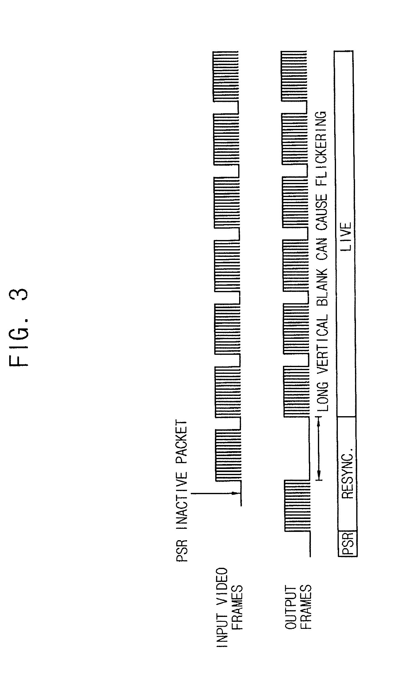
However, screen flickering may occur when an image is displayed using the PSR technology.
Further, the screen flickering may deteriorate the quality of the displayed image.

Method used


Image

  • Display drive integrated circuit and image display system
  • Display drive integrated circuit and image display system
  • Display drive integrated circuit and image display system

Examples


Embodiment Construction

[0033]The inventive concept will be described more fully with reference to the accompanying drawings, in which exemplary embodiments thereof are shown. The present inventive concept may, however, be embodied in many different forms and should not be construed as limited to the embodiments set forth herein. Like reference numerals refer to like elements throughout this application.

[0034]It will be understood that when an element is referred to as being “connected” or “coupled” to another element, it can be directly connected or coupled to the other element or intervening elements may be present. As used herein, the singular forms “a,”“an” and “the” are intended to include the plural forms as well, unless the context clearly indicates otherwise.

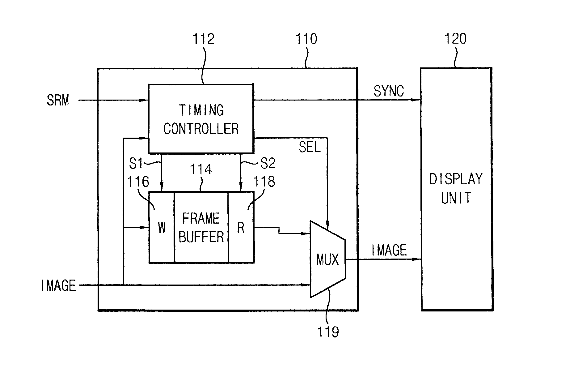
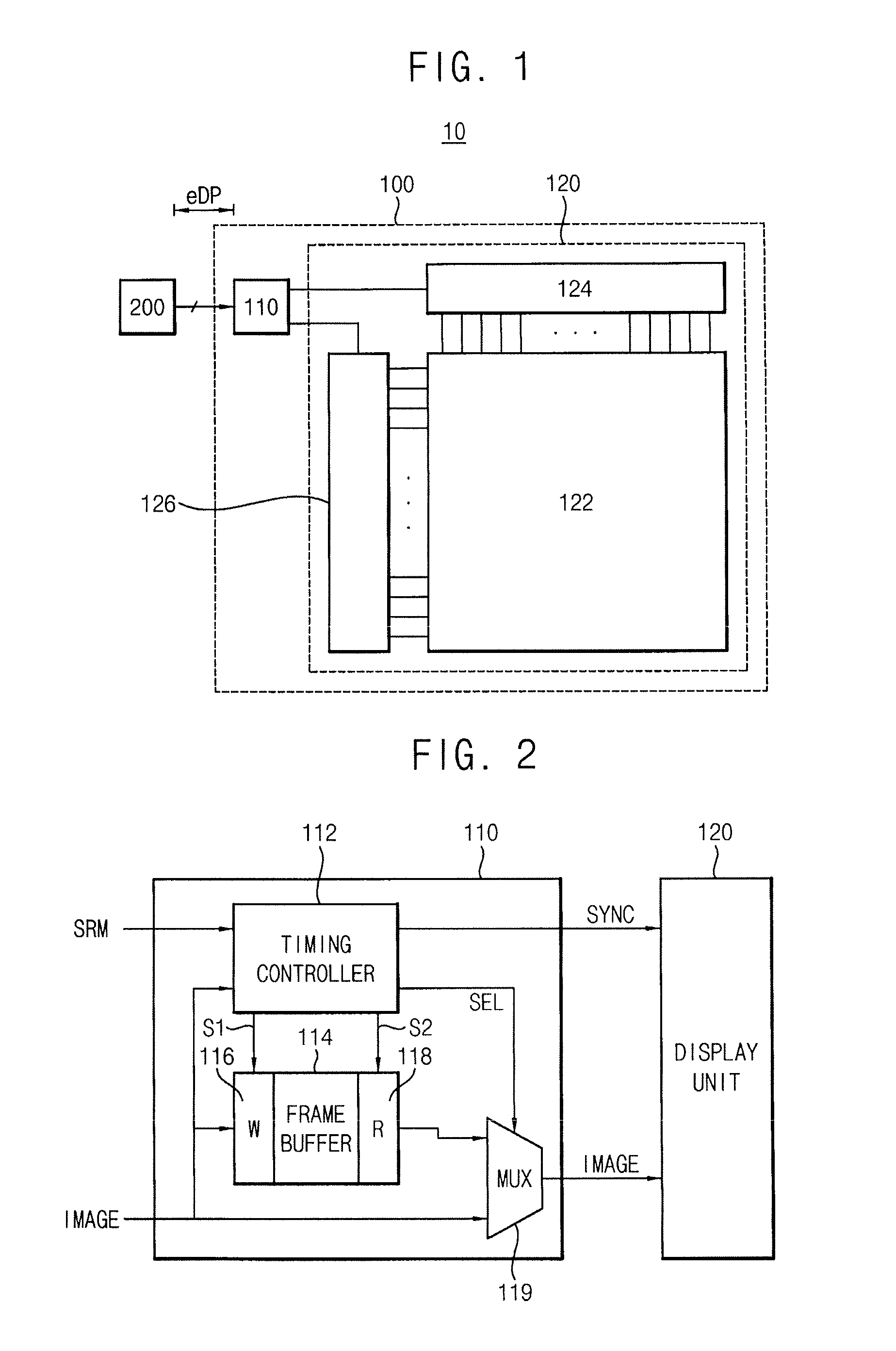
[0035]FIG. 1 is a block diagram illustrating an image display system according to an exemplary embodiment of the inventive concept.

[0036]Referring to FIG. 1, the image display system 10 according to an exemplary embodiment of the inventive conc...


PUM


Abstract

A display drive integrated circuit includes a frame buffer, an output selector and a timing controller. The output selector selectively outputs one of image data read from the frame buffer and image data transmitted from a source external to the display drive integrated circuit. The timing controller controls output of the image data read from the frame buffer to the display panel in a self-refresh mode, and controls internal display timing to track external display timing when the display drive integrated circuit exits from the self-refresh mode to control the output selector to output the image data transmitted from the source to the display panel when the internal display timing is synchronized to the external display timing.

Description

CROSS-REFERENCE TO RELATED APPLICATION[0001]This application claims priority under 35 USC §119 to Korean Patent Application No. 10-2013-0024236, filed on Mar. 7, 2013, in the Korean Intellectual Property Office (KIPO), the disclosure of which is incorporated by reference in its entirety herein.BACKGROUND[0002]1. Technical Field[0003]Exemplary embodiments of the inventive concept relate generally to a display drive integrated circuit (hereinafter, referred to as “display drive IC”) and an image display system, and more particularly to a display drive IC and an image display system capable of controlling a self-refresh display.[0004]2. Discussion of Related Art[0005]A smart phone may include a high resolution display, which receives an image signal from a host through a display drive IC to display the image signal. However, when the display receives a still image from the host, power may be consumed unnecessarily.[0006]A panel self-refresh (PSR) technology may be used to display an im...

Claims


Application Information

Patent Timeline
Patent Type & Authority Applications(United States)
IPC IPC(8): G09G5/12
CPCG09G5/12G09G5/003G09G5/006G09G2320/103G09G2330/021G09G2360/18G09G2370/04G09G2370/10G09G3/20
Inventor LEE, JONG-SUNGOH, SE-MOONKIM, BYUNG-KOANWAI, DUSTIN YUK LUNJUNG, HYE-JIN
Owner SAMSUNG ELECTRONICS CO LTD
Learn More