Sectionalized arrow

Inactive Publication Date: 2014-09-11
FLINT G WILSON
View PDF4 Cites 15 Cited by
  • Summary
  • Abstract
  • Description
  • Claims
  • Application Information

AI Technical Summary

Benefits of technology

[0005]In accordance with the present invention, a two-part sectionalized arrow is provided that can be assembled by joining a nock section with a tip section. In overview, the tip section and the nock section are both elongated shafts having a respective fore-end and a respective aft-end. For their assembly, an insert is formed onto the fore-end of the nock section, and a hollow chamber is formed into the aft-end of the tip section. A shim that is attached to the insert and is positioned between the insert and the inside of the hollow chamber promotes an interaction between the insert and the chamber that establishes a snug fit between the two sections when the insert of the nock section is received into the aft-end of the tip section.
[0009]An important component of the present invention is a longitudinal shim or strip of coating material that is preferably located on the insert portion of the nock section. As envisioned for the present invention, when sections of the arrow are joined together, the shim or strip of coating material will be positioned between the inside surface of the hollow chamber of the tip section and the outer surface of the insert portion of the nock section. As a consequence, the shim will force a large fraction of the outer surface of the insert into contact with the inner surface of the chamber to establish a snug fit between the two.
[0011]It is well-known that the aerodynamic performance of an arrow improves with the straightness of an arrow. Thus, in accordance with the present invention, a simple procedure is provided to ensure the sectionalized arrow is as straight as possible, when assembled. To accomplish this, analyses of both the tip section and the nock section of an arrow are conducted to identify their respective planes of curvature after each section of the arrow has been manufactured. These two planes of curvature are then oriented next to one another in a coplanar arrangement. When the two sections are coplanar, they can be oriented so the net effect of the curvature on the assembled arrow is minimized. Specifically, as with any arrow, the goal here is to minimize the effect of curvature. Once the planes are aligned in this way, a first index mark is placed onto the fore-end of the nock section and a second mark is placed on the aft-end of the tip section. Further, in order to ensure these same sections are used with each other when there is a set of arrows, the marks for each particular arrow may be color coded. Operationally, these index marks can then be aligned by a user during a later assembly of the arrow to ensure the effect of curvature is minimized.

Problems solved by technology

Further, for hunting activities, a hunter will most likely spend several hours, and may very well spend several days, in an isolated area.

Method used


Image

  • Sectionalized arrow
  • Sectionalized arrow
  • Sectionalized arrow

Examples


Embodiment Construction

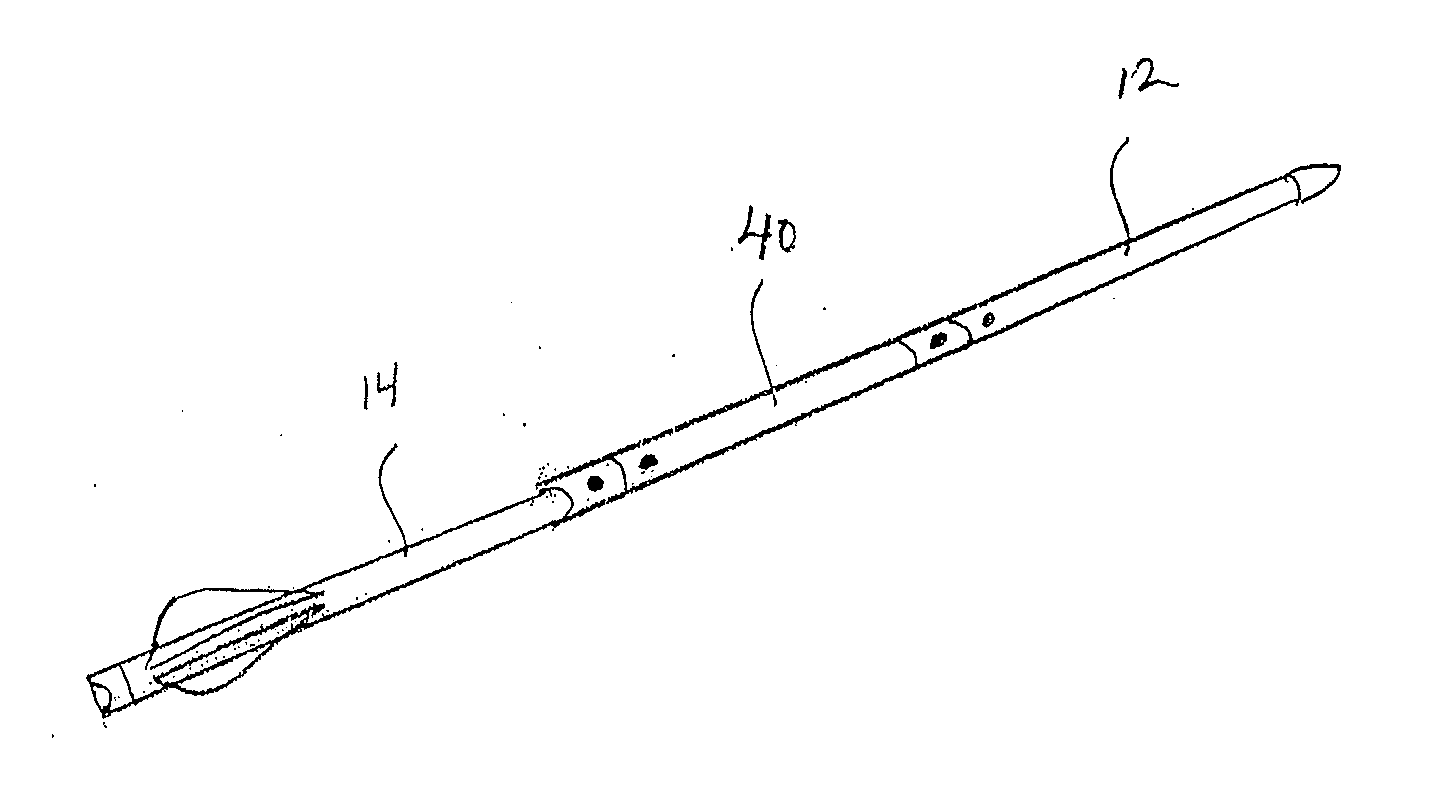
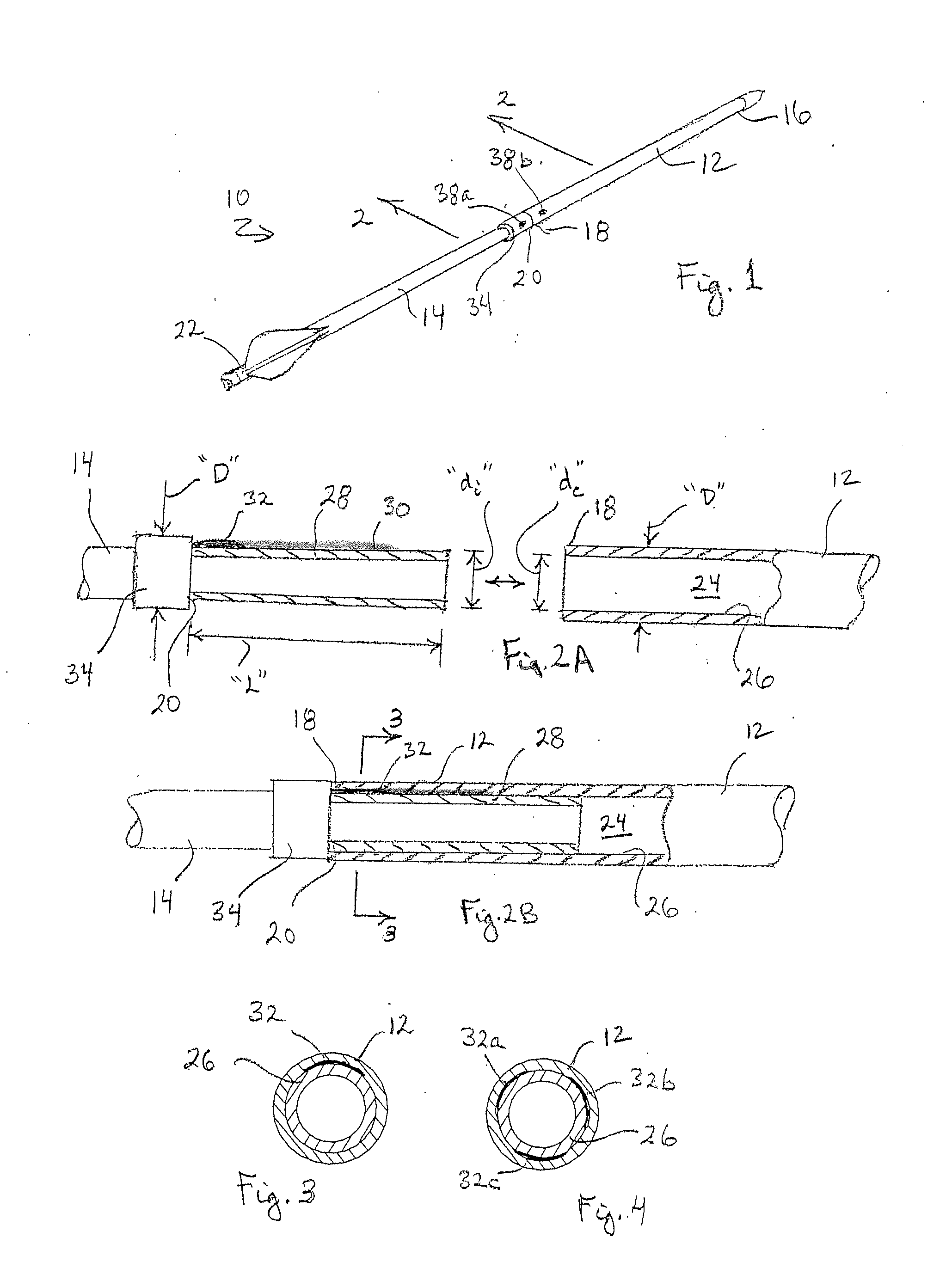
[0023]Referring initially to FIG. 1, a sectionalized arrow in accordance with the present invention is shown and is generally designated 10. As shown, the arrow 10 includes a tip section 12 and a nock section 14. Further, the tip section 12 has a fore-end 16 and an aft-end 18. Similarly, the nock section 14 has a fore-end 20 and an aft-end 22.

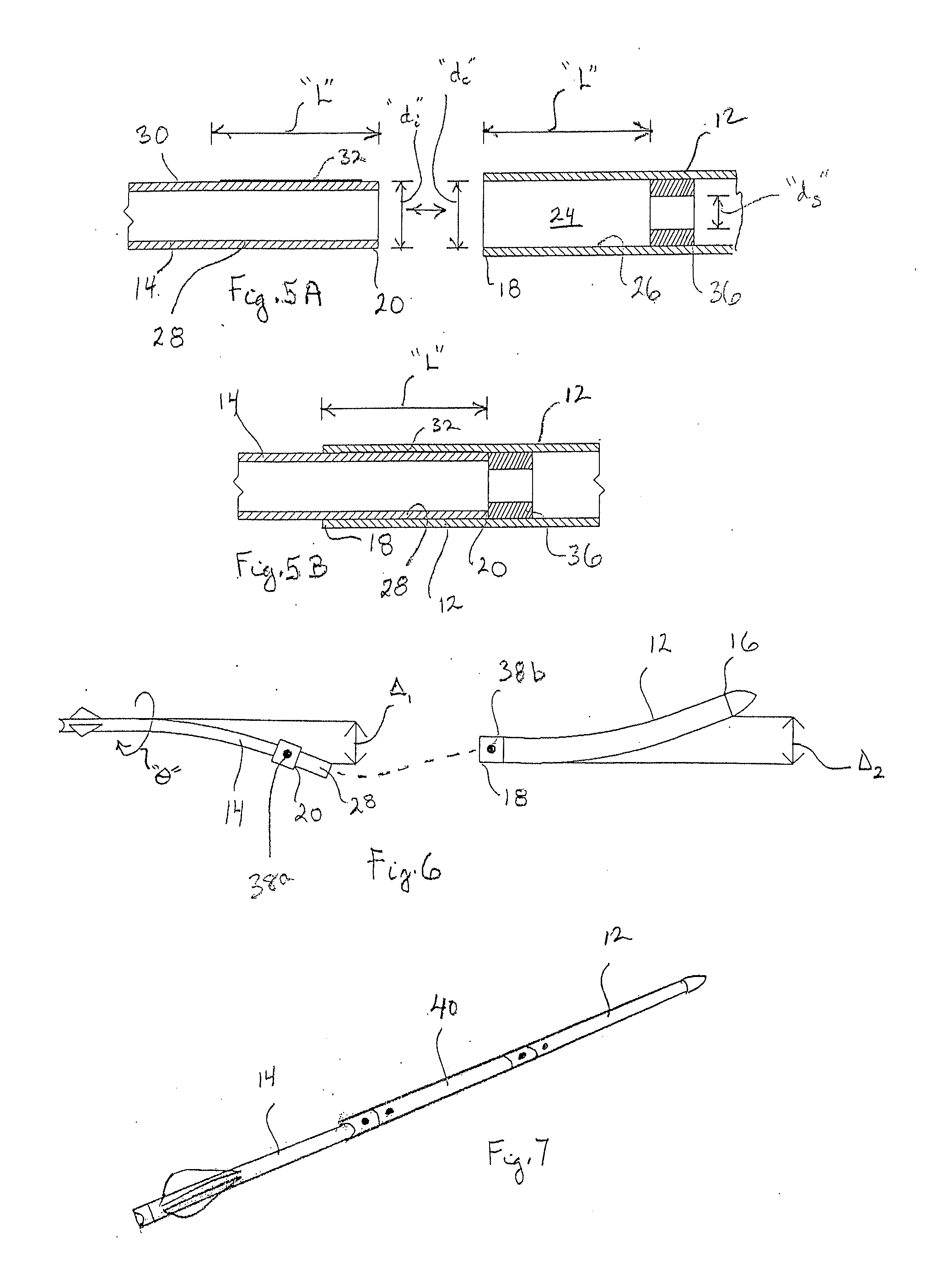
[0024]In FIG. 2A it will be seen that the tip section 12 is essentially a hollow, tubular-shaped structure that is formed with a chamber 24 inside the aft-end 18 of the tip section 12. Further, the tip section 12 is shown to have an outer diameter “D”, and the chamber 24 is shown to have a diameter “dc”. Similarly, it will be seen in FIG. 2A that, like the tip section 12, the nock section 14 is also essentially a hollow, tubular-shaped structure. The nock section 14, however, is formed with an insert 28 that extends axially from the fore-end 20 of the nock section 14. As shown, the insert 28 has a length “L” and it has an outer surface 30 with ...


PUM

PropertyMeasurementUnit
lengthsaaaaaaaaaa
outer diameteraaaaaaaaaa
diameteraaaaaaaaaa

Abstract

A sectionalized arrow includes a tubular-shaped tip section and a tubular-shaped nock section. Structurally, the aft-end of the tip section is formed with a chamber, and the fore-end of the tip section is formed with an insert. Essentially, the insert of the nock section and the chamber of the tip section have the same length “L”. A shim or strip of coating is positioned on the insert of the nock section to force contact between the insert and the chamber to establish a snug fit between the tip section and the nock section.

Description

FIELD OF THE INVENTION[0001]The present invention pertains generally to arrows that are suited for use with man-powered weapons, such as a conventional bow, a compound bow or a crossbow. More particularly, the present invention pertains to arrows that can be assembled, onsite, by the user. The present invention is particularly, but not exclusively, useful as an arrow that can be broken down into sections for ease of transport, and subsequently assembled, as desired, to establish an aerodynamically suitable arrow.BACKGROUND OF THE INVENTION[0002]When so-called “man-powered” weapons, such as a crossbow or a compound bow, are used for hunting or target shooting, a person will usually carry most of the equipment required for participating in these activities. Typically, the primary means of transportation for these activities will be travelling on foot. In most instances, a person will carry the weapon, arrows, spare parts, and tools required to use or service the weapon. Further, for h...

Claims


Application Information

Patent Timeline
Patent Type & Authority Applications(United States)
IPC IPC(8): F42B6/04
CPCF42B6/04Y10T29/49826
Inventor FLINT, G. WILSON
Owner FLINT G WILSON
Why Eureka
Try Eureka