Tool changer for machine tool

a tool changer and machine tool technology, applied in the field of machine tools, can solve the problems that the tool changer or tool changing mechanism of the machine tool does not provide a stabilizing structure or mechanism, and achieve the effect of stably, smoothly replacing and changing the tool, and stable operation

Inactive Publication Date: 2014-09-11
YI CHUN LIU
View PDF15 Cites 20 Cited by
  • Summary
  • Abstract
  • Description
  • Claims
  • Application Information

AI Technical Summary

Benefits of technology

[0008]The primary objective of the present invention is to provide a machine tool including a tool changer or tool changing mechanism for suitably and stably and smoothly replacing and changing tool elements to a working spindle and for allowing the tool elements to be stably and smoothly and effectively replaced and changed with each other.
[0010]The tool cartridge includes an extending bar pivotally attached to the lever arm with the pivot shaft for allowing the tool cartridge to be pivoted relative to the lever arm and to be moved toward or away from the working spindle and / or the guiding member.

Problems solved by technology

However, the typical tool changers or tool changing mechanisms for machine tools failed to provide a stabilizing structure or mechanism for stabilizing the tool cartridge and for allowing the tool members to be stably and suitably changed and fitted to the working spindle.

Method used


Image

  • Tool changer for machine tool
  • Tool changer for machine tool
  • Tool changer for machine tool

Examples


Embodiment Construction

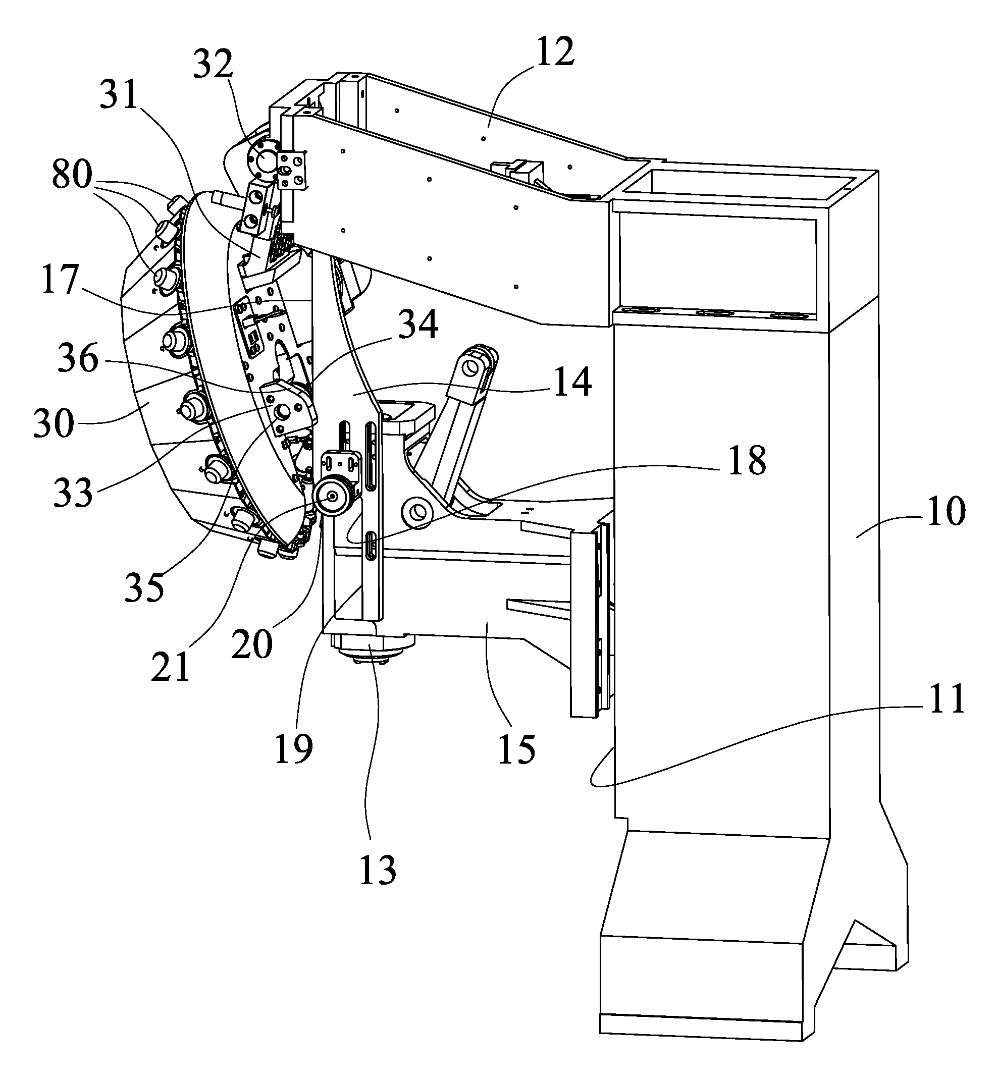
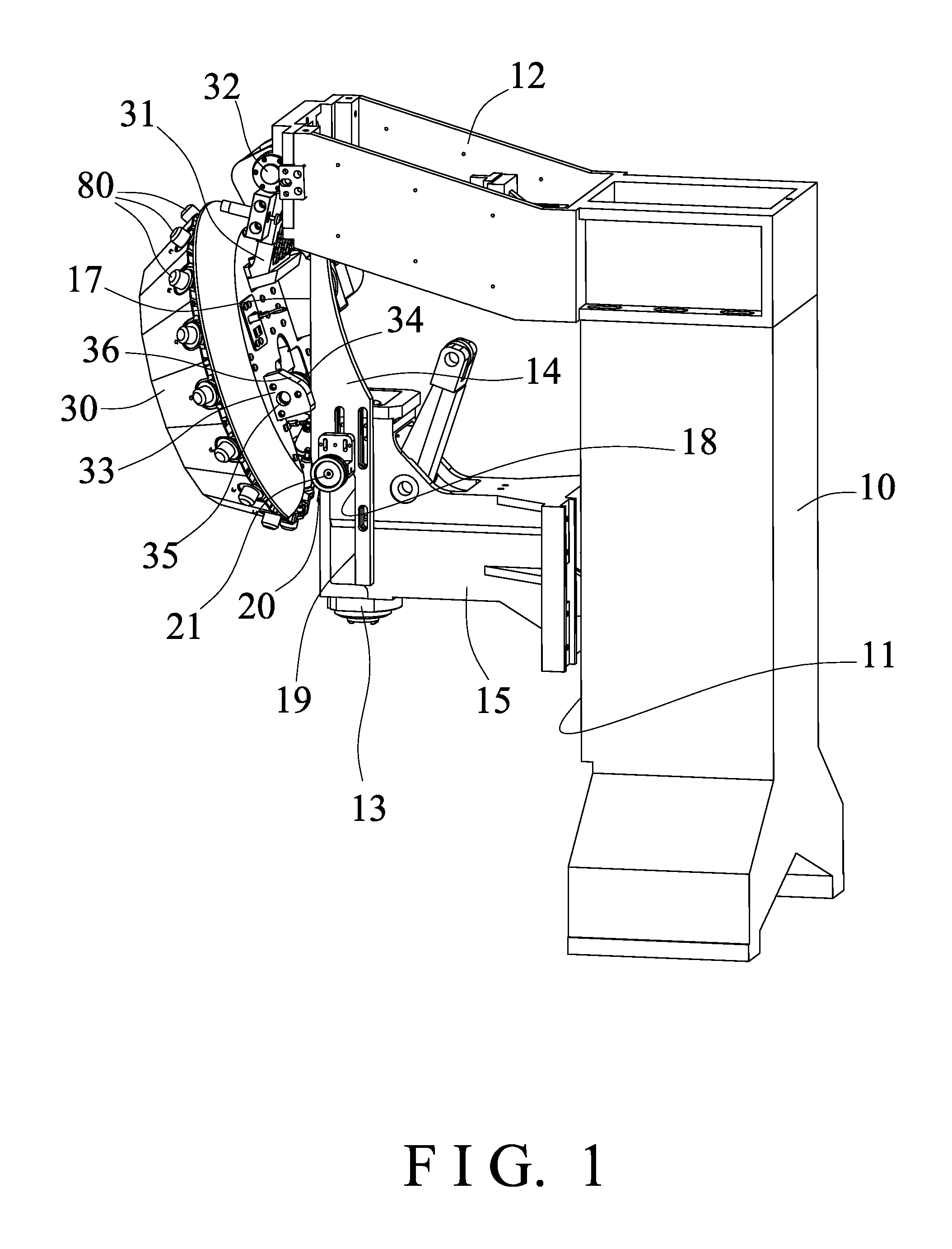
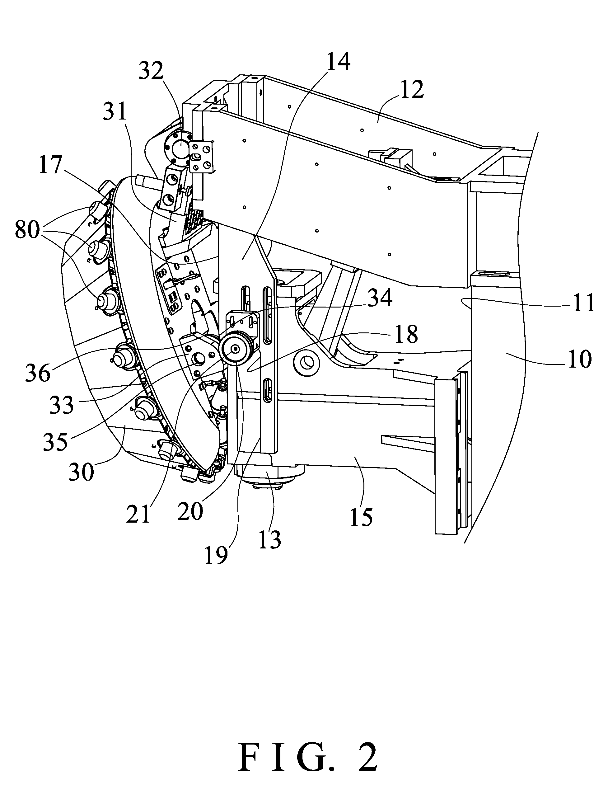
[0018]Referring to the drawings, and initially to FIGS. 1-4, a machine tool in accordance with the present invention comprises a stand or column 10 including a straight guide or guide rail 11 formed or provided on the front portion thereof, a head or arm or support or lever arm 12 provided and attached or mounted or secured or supported on top of the column 10 and extended forwardly from the column 10, a working spindle 13 and one or more (such as two) plates or boards or molding or guiding members 14 solidly and stably secured or coupled together and slidably attached or mounted or secured or coupled to the lever arm 12 and movable or slidable up and down relative to the lever arm 12 (FIGS. 5-8), the working spindle 13 and / or the guiding members 14 include an arm or slide member or extension 15 slidably attached or mounted or secured or coupled to and engaged with the guide rail 11 for guiding the working spindle 13 and the guiding members 14 to move or slide up and down along the ...


PUM


Abstract

A machine tool includes a lever arm extended from a column, a working spindle and a guiding member attached to the lever arm and having an upper guiding surface and a lower recess formed by an anchoring surface, the guiding surface is located farther away from the column as compared with the anchoring surface of the guiding member, a tool cartridge is attached to the lever arm for supplying tool elements to the working spindle, and includes a seat having a cam surface, a guiding roller attached to the seat for engaging with the guiding surface of the guiding member and for selectively separating the tool cartridge from the working spindle and the guiding member.

Description

BACKGROUND OF THE INVENTION[0001]1. Field of the Invention[0002]The present invention relates to a machine tool, and more particularly to a machine tool including a tool changer or tool changing mechanism for suitably and stably and smoothly replacing and changing tool elements to a working spindle and for allowing the tool elements to be stably and smoothly and effectively replaced and changed with each other.[0003]2. Description of the Prior Art[0004]Typical machine tools comprise a disc or tool carrier or cartridge including a number of adapters or tool mounts for removably and changeably carrying or supporting tool members thereon, and for selectively or changeably supplying or feeding or fitting the selected tool members to the working spindle of the typical machine tool for changing the tool members from one to the other.[0005]For example, U.S. Pat. No. 4,776,081 to Okunishi et al., U.S. Pat. No. 5,762,594 to Hoppe, U.S. Pat. No. 6,102,840 to Xiao, U.S. Pat. No. 7,387,600 to S...

Claims


Application Information

Patent Timeline
Patent Type & Authority Applications(United States)
IPC IPC(8): B23Q3/157
CPCB23Q3/15706B23Q3/15506B23Q3/15526B23Q3/15534B23Q3/1572Y10T483/1755Y10T483/179Y10T483/1795
Inventor LIU, CHE SEN
Owner YI CHUN LIU
Why Eureka
Try Eureka