
Tire testing machine

a technology of tire testing machine and roller, which is applied in the direction of vehicle testing, way, structure/machine measurement, etc., can solve the problems of tire sliding relative to the conveyor, affecting the running performance of the automobile or the like, and affecting the performance of the vehicle or the lik

Active Publication Date: 2014-09-18
KOBE STEEL LTD
View PDF2 Cites 20 Cited by
  • Summary
  • Abstract
  • Description
  • Claims
  • Application Information

AI Technical Summary

Benefits of technology

The patent is for a tire testing machine that has a mechanism to change the distance between two rims along a y axis, which is controlled by a spindle actuator. The machine also has a conveyor that moves the tire being tested along an x axis, which is driven by a conveyor actuator. A motion controller uses the position feedback of the conveyor along x axis to control the spindle actuator to change the distance between the rims along the y axis in synchronization with the movement of the conveyor along the x axis. The technical effect of this invention is to provide a more accurate and precise method for testing tires by simulating the movement of the tire in a real-world driving scenario.

Problems solved by technology

When a tire attached to an automobile or the like includes a portion that has a non-uniform dimensional shape or a non-uniform elastic modulus in the circumferential direction, such portion causes a vibration during a high-speed rotation, and degrades the running performance of the automobile or the like.
Meanwhile, when the chucking mechanism that drives one or both spindles including the upper and lower rim members is operated with excessive acceleration speed or an excessive deceleration speed in order to shorten the cycle time, a problem arises in that the actuator(s) increase in size and cost and component wear increases.
Further, when the speed of the tire testing machine conveyor, itself, increases, a problem arises in that the tire may slip relative to the conveyor and not be conveyed as intended or expected on the conveyor.

Method used


Image

  • Tire testing machine
  • Tire testing machine
  • Tire testing machine

Examples


Embodiment Construction

[0023]One or more embodiments of a tire testing machine provided in accordance with the present development are described below with reference to the drawings. It is not intended that the present development be limited to the particular embodiment(s) disclosed herein, and a tire testing machine according to the present development may be modified into various forms in accordance with the claims.

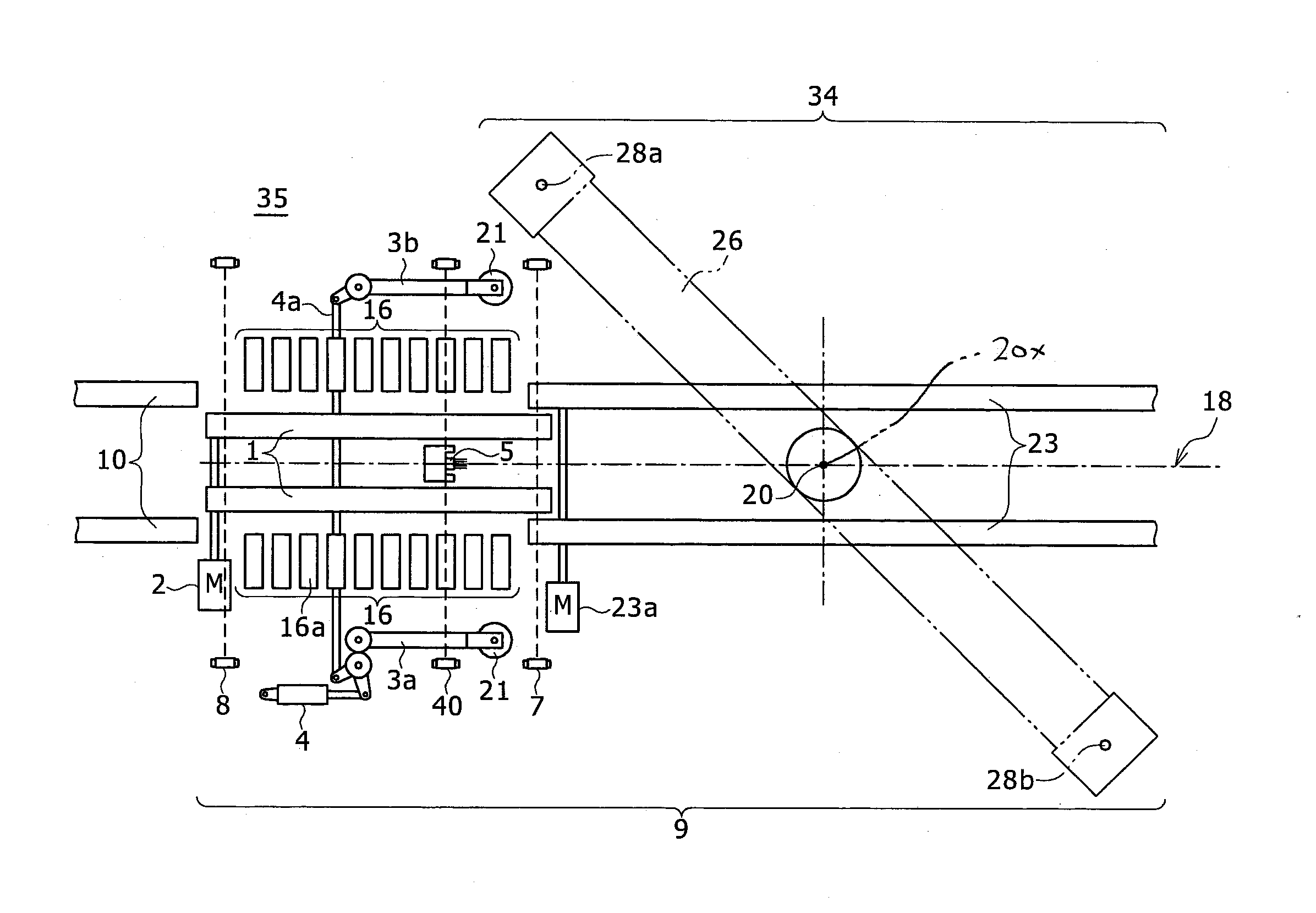
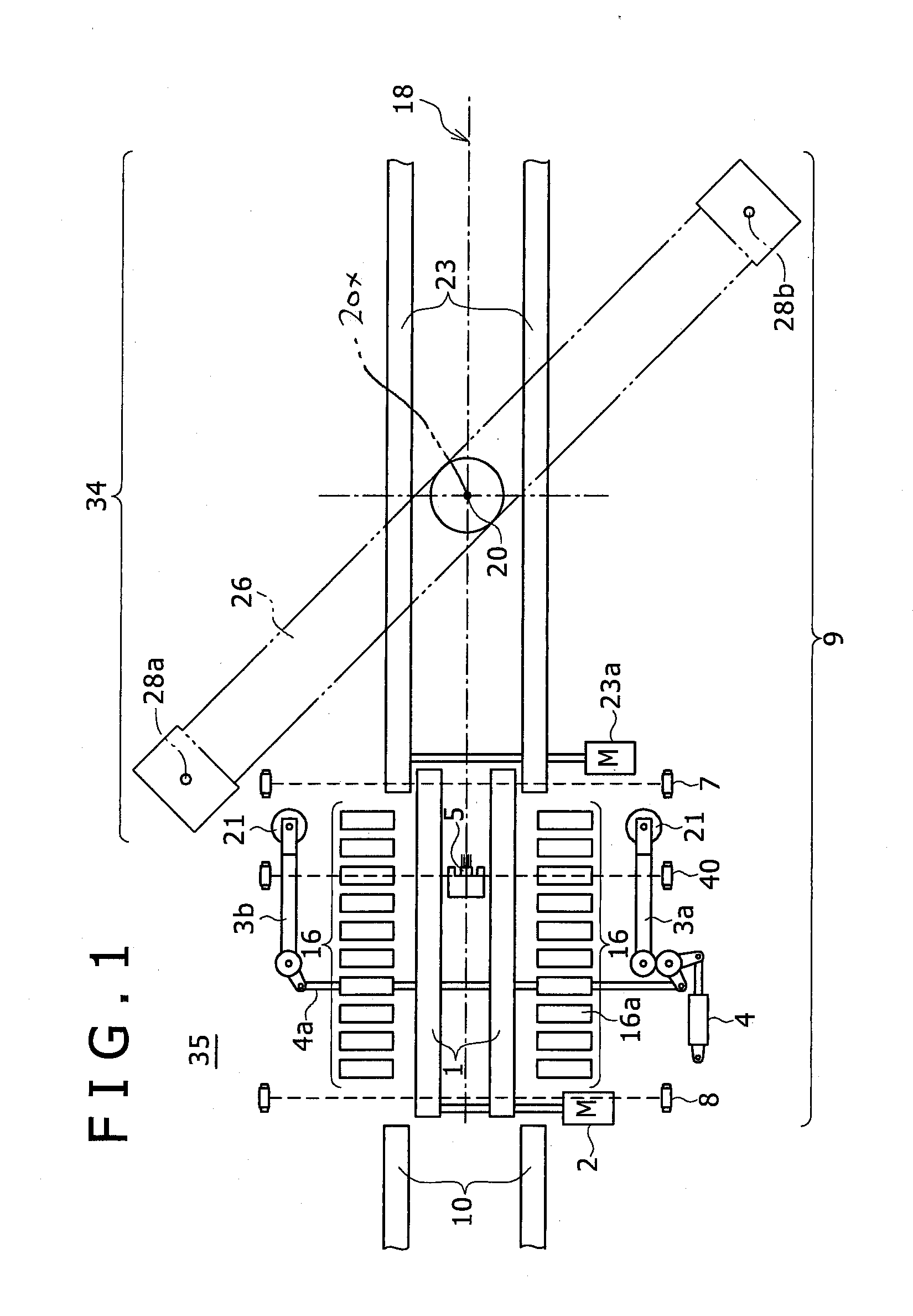
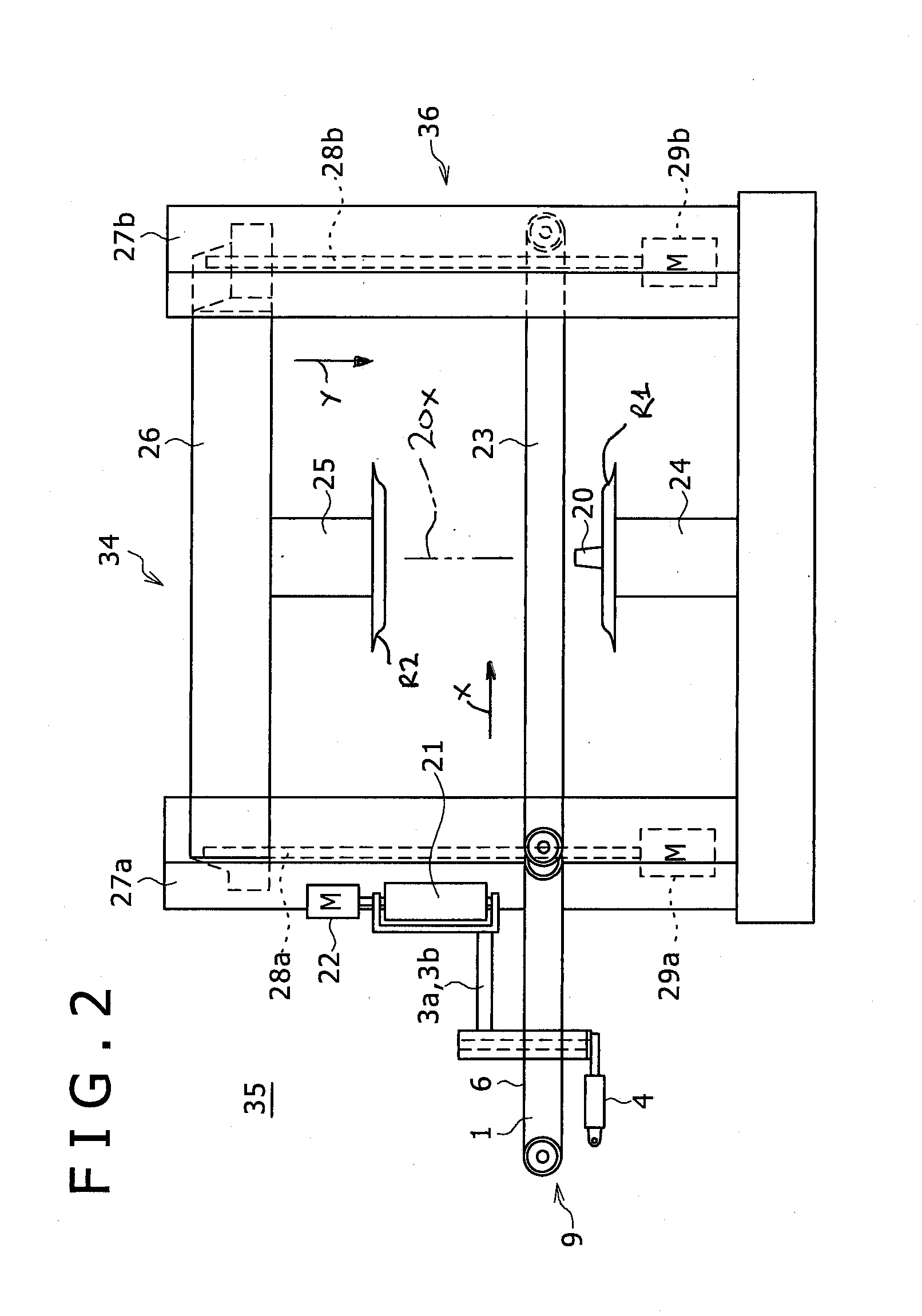
[0024]As illustrated in FIGS. 1 to 3, a tire testing machine conveyor 9 that is used in a tire testing machine 35 according to the present development includes an entrance conveyor 1 comprising a first belt conveyor that conveys an associated tire 11 that is to be tested from an upstream supply conveyor 10 to a main or center conveyor 23 comprising a second belt conveyor that is located adjacent and / or connected to the downstream side of the entrance conveyor 1 and extends into a test station 34. In the example illustrated in the drawings, each of the entrance conveyor 1 and the center convey...


PUM


Abstract

A tire uniformity testing machine includes an upper spindle including an upper rim portion, a lower spindle including a lower rim portion, and a spindle actuator such as a servo actuator adapted to vary a distance between the upper and lower spindles along a y axis. The tire testing machine also includes a conveyor adapted to move an associated tire to be tested along an x axis in a conveying direction. The conveyor is driven by a conveyor actuator said as a servo actuator. A motion controller is provided and receives x axis position feedback indicating a conveying distance moved by the conveyor along said x axis and that uses the x axis position feedback to control the spindle actuator to vary the distance between the upper and lower spindles along the y axis according to a function y=F(x) for coordinated synchronous variation of the distance between the upper and lower spindles along the y axis in response to movement of the conveyor along the x axis. The conveyor also moves vertically along the y axis and its position along with y axis can also be controlled by a servo actuator for coordinated vertical movement as a function of said x axis position feedback and / or as a function of y axis position feedback provided by said spindle actuator indicating a distance between said lower and upper spindles.

Description

CROSS-REFERENCE TO RELATED APPLICATION[0001]This application claims priority from and benefit of the filing date of U.S. provisional application Ser. No. 61 / 794,567 filed Mar. 15, 2013, and the entire disclosure of said provisional application is hereby expressly incorporated by reference into the present specification.FIELD[0002]The present development relates to a tire testing machine that tests a tire conveyed by a tire testing machine conveyor.BACKGROUND[0003]When a tire attached to an automobile or the like includes a portion that has a non-uniform dimensional shape or a non-uniform elastic modulus in the circumferential direction, such portion causes a vibration during a high-speed rotation, and degrades the running performance of the automobile or the like. For this reason, the tire is subjected to a circumferential uniformity test by a tire testing machine after a vulcanizing process. The tire testing machine performs a test in a manner such that a bead portion of the inner ...

Claims


Application Information

Patent Timeline
Patent Type & Authority Applications(United States)
IPC IPC(8): G01M17/02
CPCG01M17/02G01M17/021
Inventor VERNYI, DALE A.THOMPSON, GLEN R.
Owner KOBE STEEL LTD
Learn More