Tire uniformity testing device and tire uniformity testing method

a tire uniformity and testing device technology, applied in vehicle testing, structural/machine measurement, ways, etc., can solve problems such as time consumption, and achieve the effect of accurate tire uniformity and highly precise tire uniformity

Active Publication Date: 2014-08-21
KOBE STEEL LTD
View PDF5 Cites 11 Cited by
  • Summary
  • Abstract
  • Description
  • Claims
  • Application Information

AI Technical Summary

Benefits of technology

[0037]According to the tire uniformity testing device and the tire uniformity testing method of the present invention, it is possible to obtain the accurate tire uniformity from the measurement waveform immediately after the rotation direction of the tire is switched from the normal rotation direction to the reverse rotation direction during the tire uniformity measurement.
[0038]Further, according to the tire uniformity testing technology of the present invention, it is possible to highly precisely obtain the accurate tire uniformity, and particularly, the radial force variation (RFV) immediately after the rotation direction of the tire is switched from the normal rotation direction to the reverse rotation direction during the tire uniformity measurement.

Problems solved by technology

Thus, there is a need to measure the uniformity of the tire while the uniformity waveform is stabilized after a user waits for the restoration of the tire, and hence a problem arises in that some time is taken.

Method used


Image

  • Tire uniformity testing device and tire uniformity testing method
  • Tire uniformity testing device and tire uniformity testing method
  • Tire uniformity testing device and tire uniformity testing method

Examples


first embodiment

[0059]A first embodiment of a tire uniformity testing device and a tire uniformity testing method according to the present invention will be described with reference to the drawings.

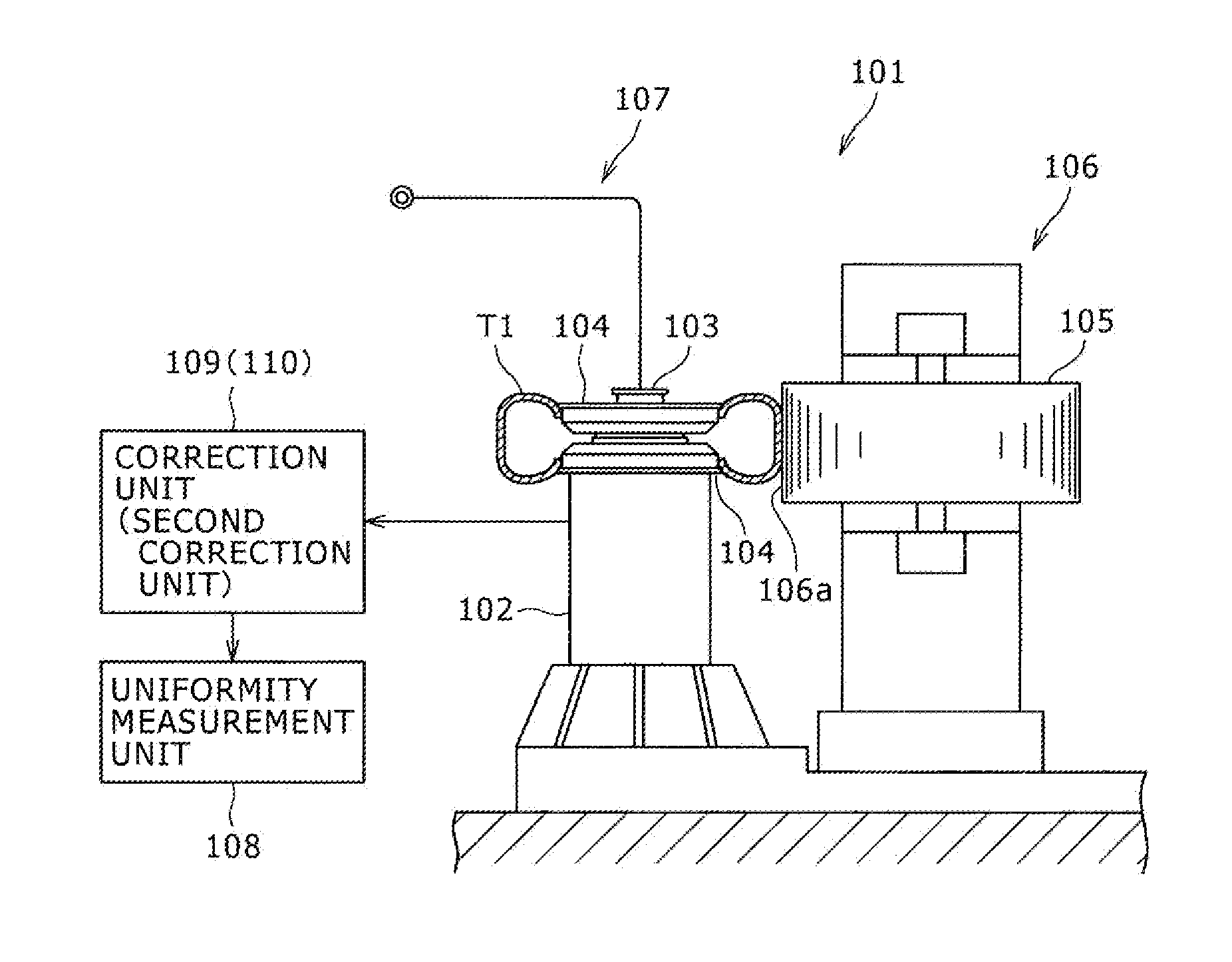
[0060]As illustrated in FIG. 1, a tire uniformity testing device 101 of the first embodiment includes a cylindrical frame body 102 that is disposed so that the axis center thereof faces the vertical direction and a spindle shaft 103 that is attached into the frame body 102 so as to be rotatable about the vertical axis through a bearing portion. The spindle shaft 103 protrudes upward from the upper end of the frame body 102, and a pair of upper and lower rims 104 and 104 is provided at the upward protruding portion of the spindle shaft 103 so as to fix a tire T1. Further, a drum (load drum) 105 having a simulation road surface 106a formed on the outer peripheral surface thereof is provided beside the tire T1 fixed by the rims 104. The drum 105 is provided in a drum mechanism 106.

[0061]The drum mechanism 1...

second embodiment

[0086]Next, a second embodiment of the tire uniformity testing device and the tire uniformity testing method according to the present invention will be described with reference to the drawings.

[0087]The second embodiment is largely different from the first embodiment in that a second correction unit 110 is provided instead of the correction unit 109 of the first embodiment and the second correction unit 110 is configured to store the uniformity waveform from the time earlier than the uniformity waveform measurement start time and to correct the RFV waveform from the early time so that the shift gradient α′ obtained from the RFV waveform is eliminated from the early time.

[0088]Furthermore, the other configurations are substantially the same as those of the first embodiment, and hence the description thereof will not be repeated.

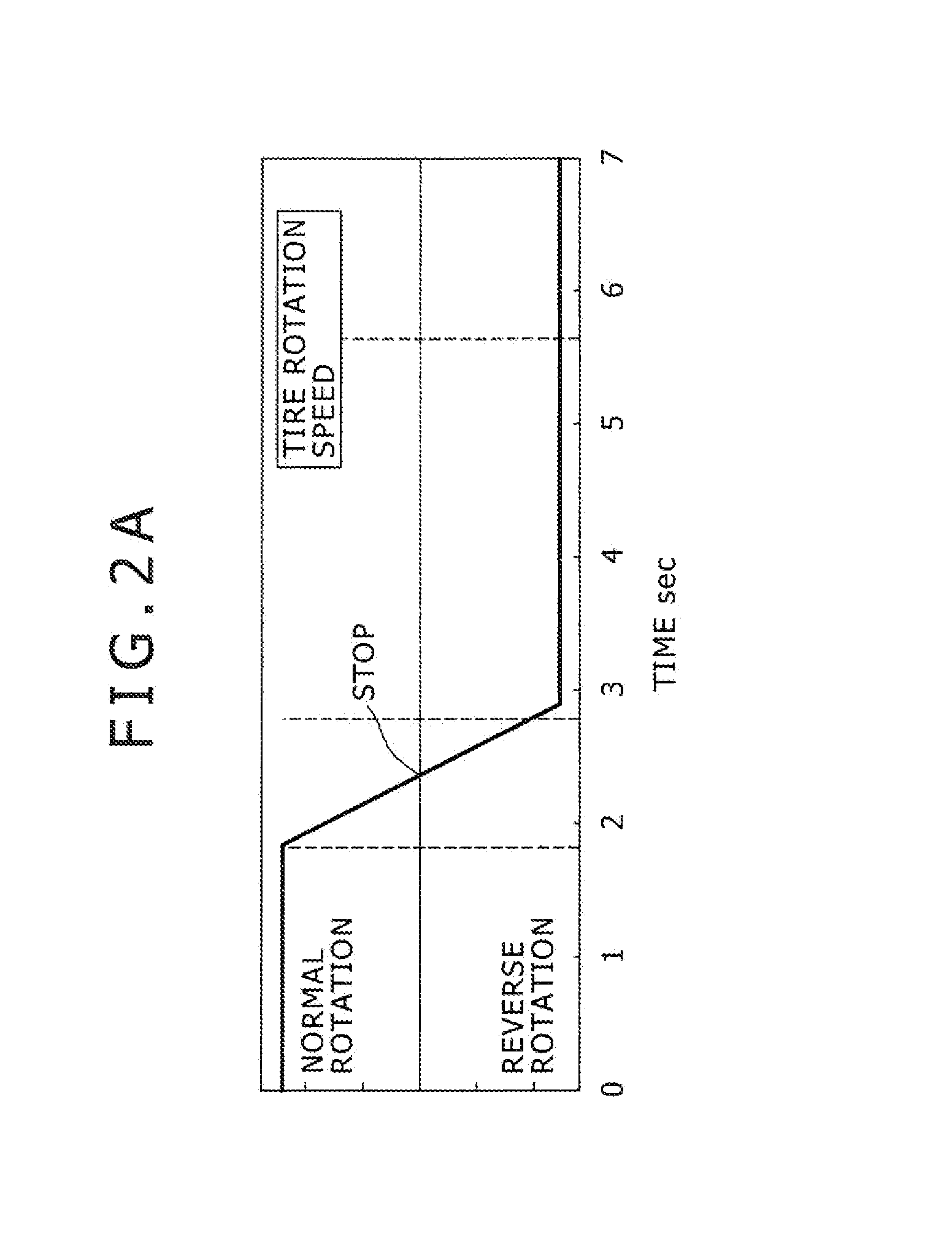
[0089]As in the first embodiment, first, the drum position starts to retreat immediately before the rotation speed of the tire T1 is changed during the normal...

third embodiment

[0095]A tire uniformity testing device 201 and a tire uniformity testing method according to the present invention will be described with reference to the drawings.

[0096]As illustrated in FIG. 5, the tire uniformity testing device 201 evaluates the tire uniformity characteristic of the product tire T2, and particularly, a variation in force of the tire radial direction (Radial Force Variation: RFV) as the production test.

[0097]Specifically, the tire uniformity testing device 201 includes a cylindrical frame body 202 that is disposed so that the axis center thereof faces the vertical direction and a spindle shaft 203 that is attached into the frame body 202 so as to be rotatable about the vertical axis through a bearing portion (not illustrated). The spindle shaft 203 protrudes upward from the upper end of the frame body 202, and a pair of upper and lower rims 204 is provided at the upward protruding portion of the spindle shaft 203 so as to fix the tire T2. Further, a substantially ...


PUM


Abstract

In a tire uniformity measurement, accurate tire uniformity is obtained from a measurement waveform immediately after a rotation of a tire is switched from a normal rotation direction to a reverse rotation direction. A tire uniformity testing device of the present invention includes a measurement unit 108 that obtains a force variation from a uniformity waveform corrected by a correction unit 109 that corrects the uniformity waveform so as to eliminate a shift gradient α existing in the uniformity waveform measured after a rotation of a tire T1 is reversed, and further includes an air-outflow regulation member 220 that regulates an from flowing into a tire T2 when a drum 205 retreats or advances.

Description

TECHNICAL FIELD[0001]The present invention relates to a tire uniformity testing device that may measure the uniformity of a tire and a tire uniformity testing method that is performed by using the testing device.[0002]Further, the present invention relates to a testing technology of a tire uniformity testing machine, and particularly, to a tire uniformity testing technology that may improve the measurement precision of a variation in force (Radial Force Variation: RFV) in the tire radial direction.BACKGROUND ART[0003]Hitherto, a uniformity inspection has been performed which measures the uniformity (evenness) of a product tire and determines whether the tire is good or bad. For example, when a case is exemplified in which the uniformity of an automobile tire is measured, a tire test is substantially performed according to the following procedure by using a tire testing device illustrated in Patent Document 1.[0004]That is, in a case where the tire test is performed by the tire unifo...

Claims


Application Information

Patent Timeline
Patent Type & Authority Applications(United States)
IPC IPC(8): G01M17/02
CPCG01M17/022G01M17/02
Inventor OKADA, TORUMURAKAMI, MASAOMATSUBARA, YOSHIAKIIKAI, SHINICHIROU
Owner KOBE STEEL LTD
Why Eureka
Try Eureka