Suspended ceiling-mountable enclosure

a ceiling mountable, suspension technology, applied in the field of enclosures, can solve the problems of difficult installation process, difficult installation process, and difficult installation of enclosures

Active Publication Date: 2014-09-18
RGB SYST INC
View PDF6 Cites 46 Cited by
  • Summary
  • Abstract
  • Description
  • Claims
  • Application Information

AI Technical Summary

Benefits of technology

[0008]The present invention is a ceiling-mountable enclosure. In one or more embodiments, the apparatus of the present invention includes an enclosure comprising a support frame, a lightweight inner enclosure, and a back box configured for installation in a suspended ceiling. In one or more embodiments, the apparatus of the present invention includes a removable device door configured to be mounted to the support frame with a hinge assembly and machine screws. In one or more embodiments, the back box, inner enclosure, and support frame of the invention are assembled together and laid onto a suspended ceiling T-bar grid. In one or more embodiments, the support frame is attached to support members to support it from the structural ceiling. In one or more embodiments, wires, such as electrical and signal wires are routed through conduit access plates provided at the back box. In one or more embodiments, electrical or other equipment is mounted to a removable device d...

Problems solved by technology

The weight of the all steel prior art enclosure can result in installation challenges.
For example, during installation, the enclosure cannot readily be laid temporarily onto the suspended ceiling framework while an installer attempts to secure support wires between a structural support and the enclosure.
Instead the weight of the enclosure must be supported by the installer during installation, often while the installer is also standing on a ladder, making the installation process difficult a...

Method used


Image

  • Suspended ceiling-mountable enclosure
  • Suspended ceiling-mountable enclosure
  • Suspended ceiling-mountable enclosure

Examples


Embodiment Construction

[0034]In the following description, numerous specific details are set forth to provide a more thorough description of the present invention. It will be apparent to one skilled in the art, however, that the present invention may be practiced without those specific details. In other instances, well-known features have not been described in detail so as not to unnecessarily obscure the invention.

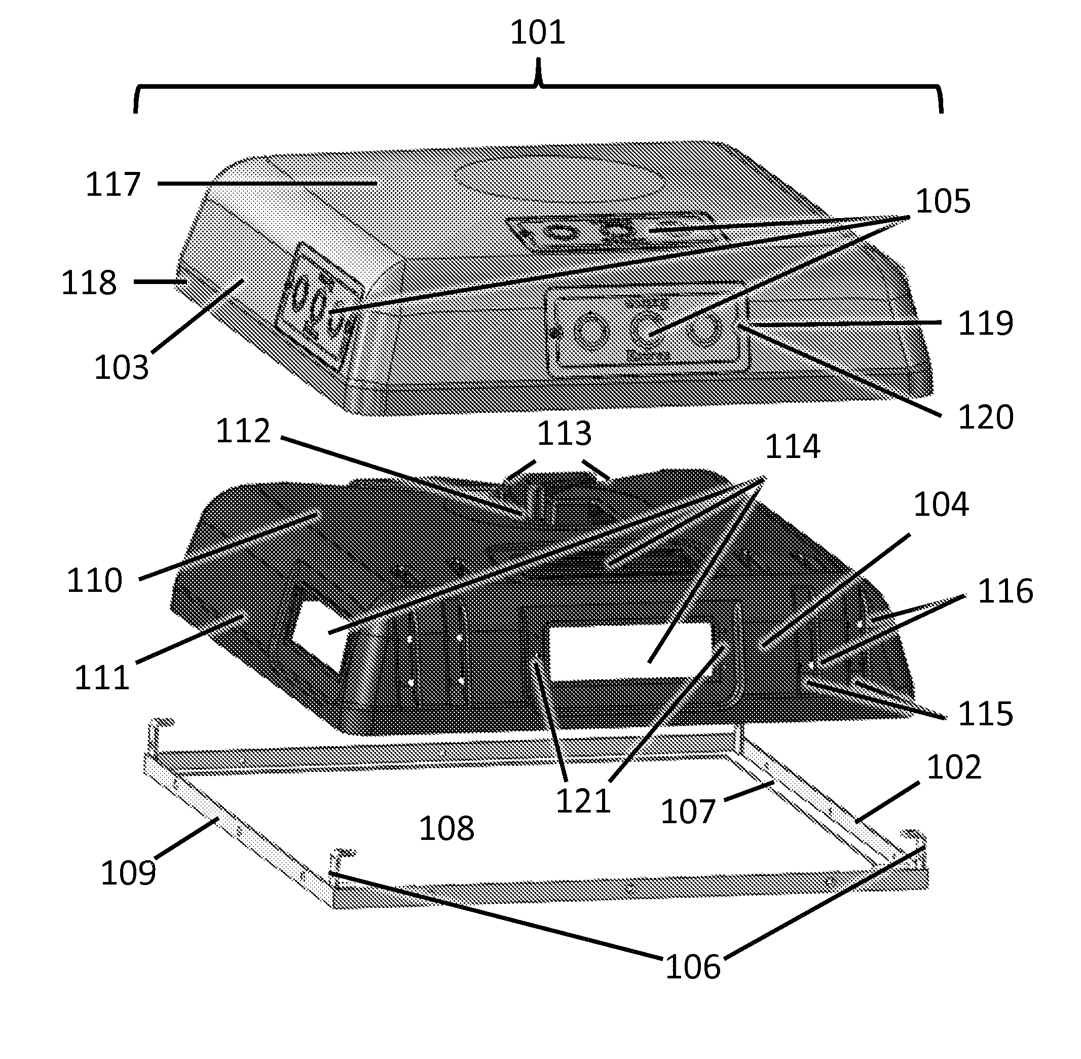
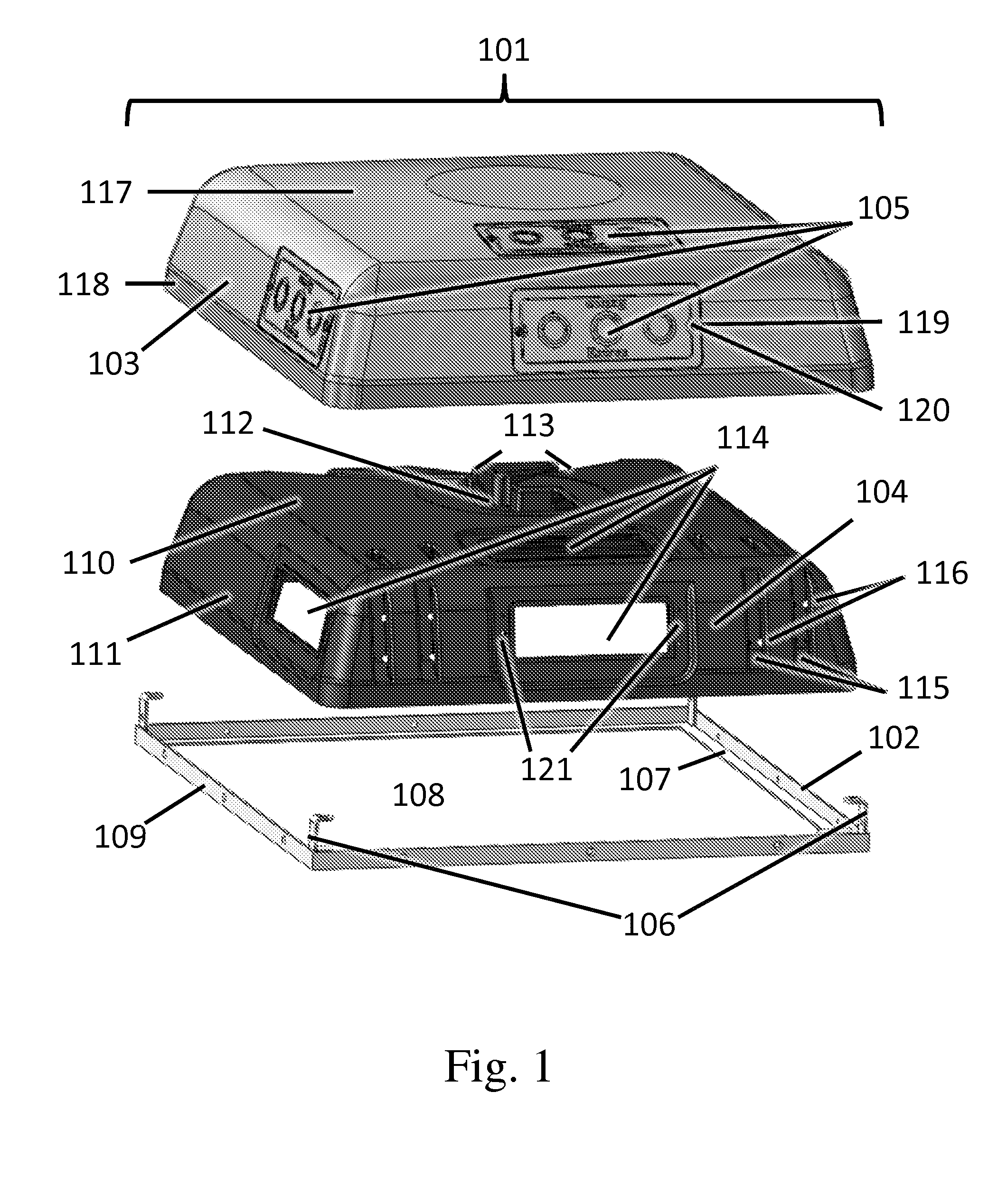
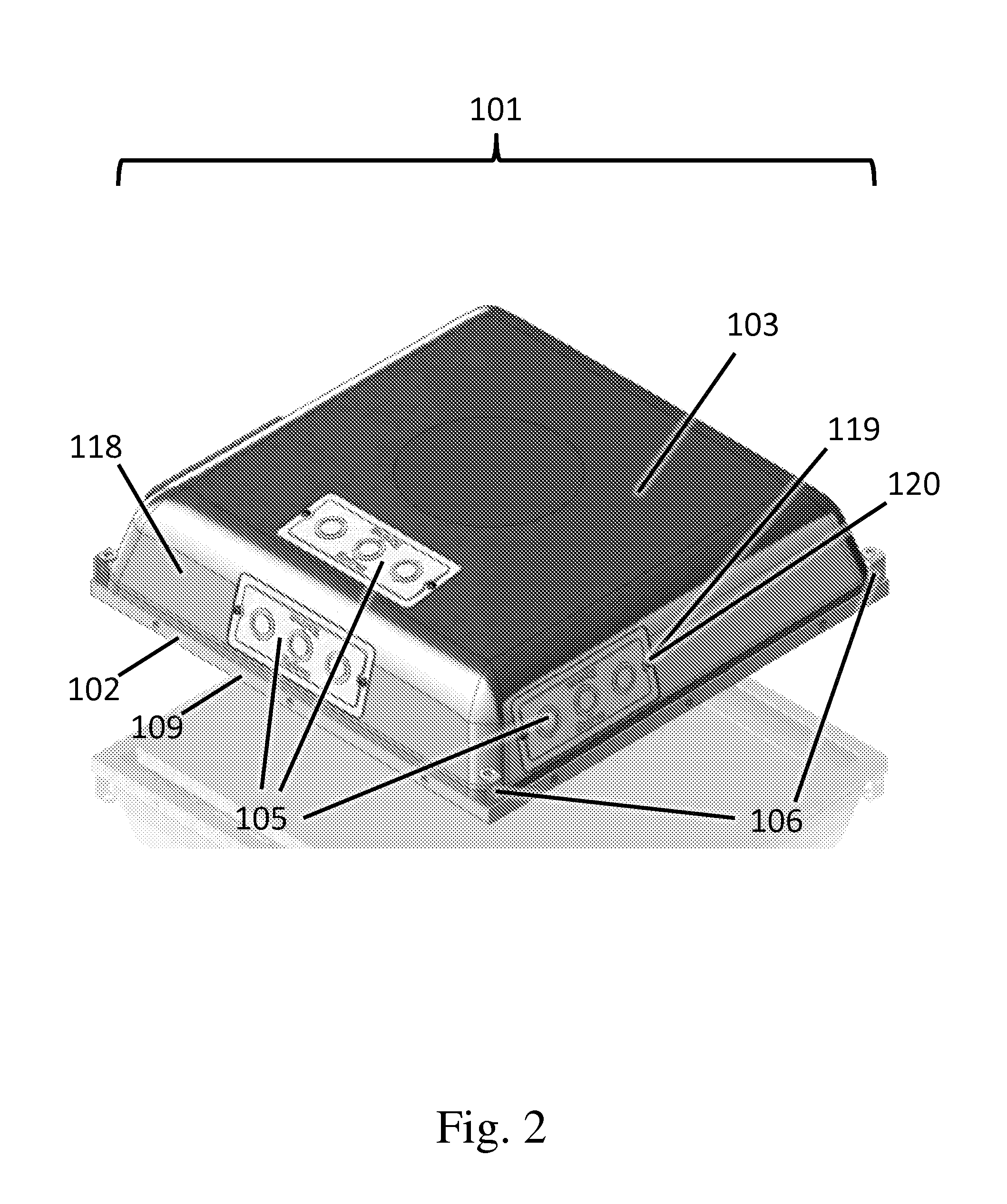
[0035]FIG. 1 is an exploded perspective view showing components of an enclosure 101 of an embodiment of the present invention. In the embodiment of FIG. 1, components of enclosure 101 include a support frame 102, a back box 103, an inner enclosure 104, conduit access plates 105, and mounting brackets 106.

[0036]In the embodiment of FIG. 1, support frame 102 is formed from steel, which has the desirable properties of high strength and rigidity. Support frame 102, however, can alternatively be formed from other suitable plastic, metal, or composite material or materials. In one or more embodiments...


PUM


Abstract

The present invention is a ceiling-mountable enclosure comprising a support frame, a lightweight inner enclosure, and a back box configured for installation in a suspended ceiling. The apparatus of the present invention includes a removable device door configured to be mounted to the support frame. Electrical and signal wires are routed through conduit access plates provided at the back box. Electrical or other equipment is mounted to a removable device door. The removable device door with mounted equipment is attached to the support frame, then rotated upwards to fit flush with the ceiling and fastened to the support frame. A variety of power receptacles are provided that are configured to be mounted to either the back box, the inner enclosure, or the removable device door. The enclosure includes a cooling system comprising an electrically powered fan and air ducts integrated into the inner enclosure.

Description

CROSS-REFERENCE TO RELATED APPLICATIONS[0001]This patent application claims the benefit of provisional U.S. Patent Application No. 61 / 785,135 filed Mar. 14, 2013 which is incorporated by reference in its entirety herein.BACKGROUND OF THE INVENTION[0002](1) Field of the Invention[0003]The present invention relates to an enclosure for electrical and other equipment configured to be mounted in a suspended ceiling.[0004](2) Background of the Invention[0005]Suspended ceilings consisting of ceiling tiles supported by a grid of T-bar frames are commonly used to form a finished ceiling in business as well as in some residential environments. It is often desired to mount electrical and other equipment in suspended ceilings. Various types of enclosures for electrical and other equipment have been developed for installation in suspended ceilings.[0006]One type of prior art enclosure that may be mounted in a suspended ceiling consists of a rectangular steel box and a removable door. The steel e...

Claims


Application Information

Patent Timeline
IPC IPC(8): F16M13/02A47B46/00H05K13/00E04B9/00A47B81/00
CPCA47B81/00A47B46/00H05K13/00F16M13/027E04B9/003H02G3/20H04R2201/021Y10T29/49117
Inventor STEWART, JR., WILLIAM CHUDSON, MICHAELVIPATAPALIN, DALETRAN, TUANEDWARDS, ANDREW C
Owner RGB SYST INC
Why Eureka
Try Eureka