Device and Method for Self-Limiting Access to Objects and Substances

a self-limiting and container technology, applied in the field of time-locking containers, can solve the problems of easy forced open, too small to store alcohol or food, and no self-control applications

Active Publication Date: 2014-09-18
INGLE MICHAEL EARL +1
View PDF4 Cites 14 Cited by
  • Summary
  • Abstract
  • Description
  • Claims
  • Application Information

AI Technical Summary

Benefits of technology

[0015]In another aspect of the device, the user may optionally enable an early open function, called a Cooldown period. When Cooldown is requested, the container will permit opening only after an unlocking delay time period elapses, and will deny opening after the relocking delay time period elapses. The Cooldown feature allows the user to satisfy an occasional, severe, and long-lasting craving, while allowing time for a short-lived craving to fade.

Problems solved by technology

All of these designs are optimized for bank vaults and / or store safes, and none have the features required for self-control applications.
These are designed only for cigarettes, are too small to store alcohol or food, and are easily forced open.
It has no early open or scheduling options beyond a single unlock time; the open time cannot be extended while locked; and it is not secure.
None of the prior art meets the need for a small, easy-to-use, secure container with specific features to enable self-control, as opposed to secure storage of money or valuables.
Existing time-locked safes are large, expensive, and made for commercial use.
The clock display and input device are usually found on the inside of the door, meaning that the user cannot see the future unlocking time, or extend the unlocking time, while the safe is locked.
These safes are usually complex to install, program, and operate, so that a locksmith is typically required.
Such safes do not include features specifically designed for the self-control user.
Many people have difficulty controlling behaviors, such as eating, drinking alcohol, smoking tobacco, or spending money.
Most people with such difficulties express the desire to limit their future behavior, but are unable to do so.

Method used


Image

  • Device and Method for Self-Limiting Access to Objects and Substances
  • Device and Method for Self-Limiting Access to Objects and Substances
  • Device and Method for Self-Limiting Access to Objects and Substances

Examples


Embodiment Construction

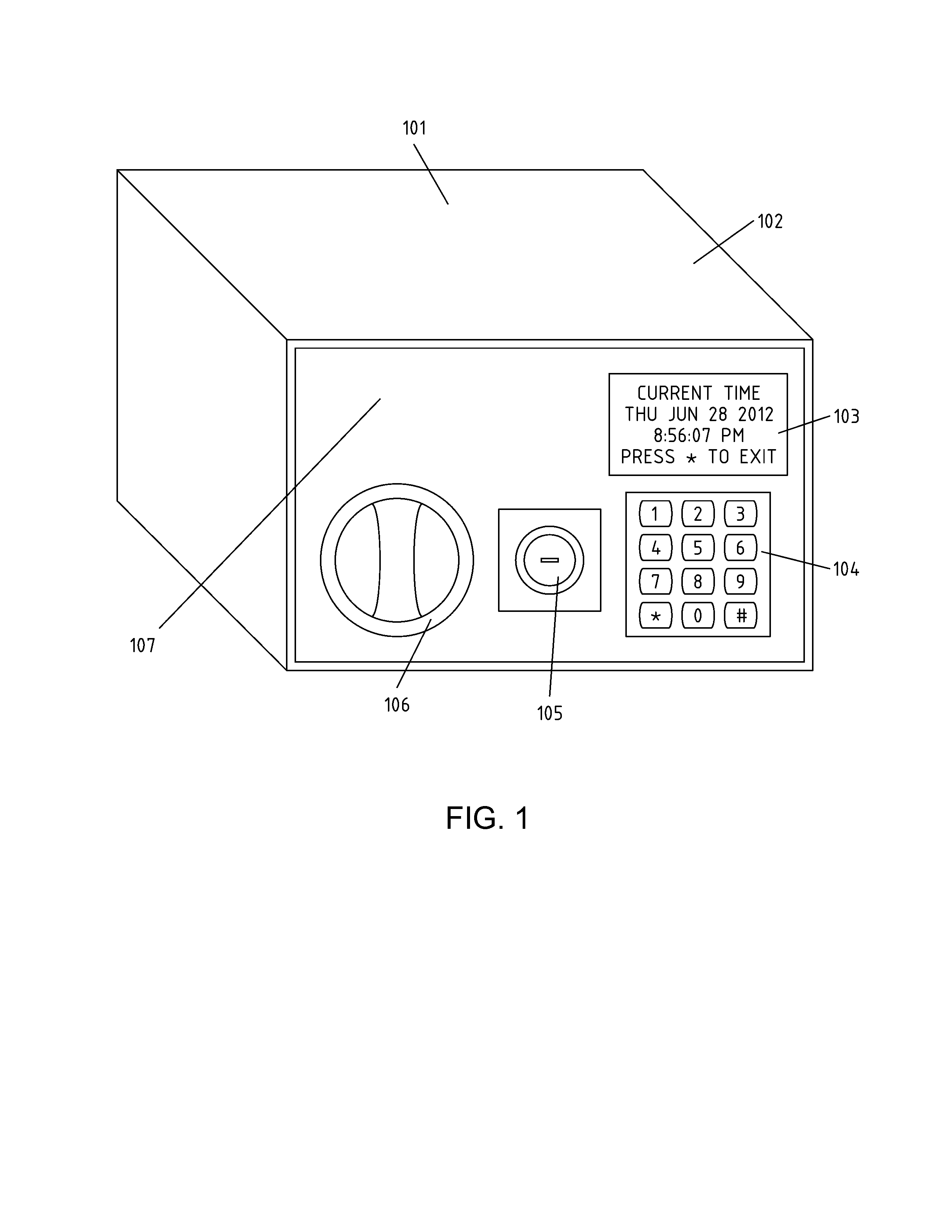
[0027]An exemplary embodiment 101 is shown in FIG. 1. The container is a metal safe 102 of the type commonly used to store valuables, with a body and a door. The door panel 107 of the safe incorporates a display 103, a keypad 104, a bypass key lock 105, and an opening knob 106. The bypass key lock is shown with its removable cover plate removed.

[0028]To open the container, the user presses one of the bottom row buttons (*, 0, or #) on the keypad 104, causing the display 103 to illuminate and display the status of the device. If the device is not time-locked, the display prompts the user to enter a numeric combination access code and press the # key. If the combination entered matches the combination stored in the device's memory, the container permits access by electrically actuating its door releasing solenoid. The user then turns the knob 106 clockwise and pulls to swing the door open.

[0029]To close the safe, the user pushes the door closed and turns the knob 106 counter-clockwise...


PUM


Abstract

A time-locking container to limit the compulsive overuse of objects and substances, such as but not limited to money, food, alcohol, and tobacco. The container locks until a future date and time of day set by the user. The container informs the user, before it locks, of the duration of locking. If the duration exceeds a user-selectable maximum, the container waits for user confirmation, otherwise it locks after a delay. This feature prevents an accidental prolonged lockout. While the container is locked, the user can extend, but not shorten, the duration of locking The user can request early access to the contents, while the container is locked, subject to an unlocking delay before access is granted, a relocking delay after which access is denied, and an inhibit delay limiting the frequency of use of the early open feature. The device provides a programmable schedule, and can relock itself after a programmable delay.

Description

CROSS-REFERENCE TO RELATED APPLICATIONS[0001]This application claims priority from U.S. Provisional Patent Application No. 61 / 786,534 filed on Mar. 15, 2013, which is incorporated herein by reference in its entirety.STATEMENT REGARDING FEDERALLY SPONSORED RESEARCH AND DEVELOPMENT[0002]Not Applicable.REFERENCE TO A SEQUENCE LISTING[0003]Not Applicable.BACKGROUND[0004]1. Field[0005]The application relates to locking containers, specifically to an improved time-locking container for self-control purposes, and to a method for its use.[0006]2. Prior Art[0007]U.S. Pat. No. 186,369 is the original patent for a mechanical time and combination lock, intended for bank vaults. This design is still commonly used today. U.S. Pat. No. 3,950,678 is an electronic time vault lock using digital logic. U.S. Pat. Nos. 4,875,351 and 5,387,903 are microcontroller-based time locks. All of these designs are optimized for bank vaults and / or store safes, and none have the features required for self-control a...

Claims


Application Information

Patent Timeline
Patent Type & Authority Applications(United States)
IPC IPC(8): G07C9/00
CPCG07C9/00007G07C1/32G07C9/00817G07C2209/08A24F15/005G07C9/00912G07C9/00896
Inventor INGLE, MICHAEL EARLDERKITT, JENNIFER LORRAINE
Owner INGLE MICHAEL EARL
Why Eureka
Try Eureka