
Shutter apparatus and image pickup apparatus

a pickup apparatus and shutter technology, applied in the direction of shutters, instruments, camera body details, etc., can solve the problems of reducing the shutter speed, so as to shorten the release time lag, quick restoring bound, and increasing shutter speed

Inactive Publication Date: 2014-09-18
CANON KK
View PDF1 Cites 5 Cited by
  • Summary
  • Abstract
  • Description
  • Claims
  • Application Information

AI Technical Summary

Benefits of technology

The present invention provides a shutter apparatus and an image pickup apparatus that can quickly return to a return operation, shorten the release time lag, and increase the shutter speed. Additionally, the invention allows for live view without the need to move the main mirror and has a simple configuration driven by a motor.

Problems solved by technology

However, in JP 2007-316503, restoring a bound of the blade groups at the return operation needs a long time.
Since a driving lever cannot be driven until the bound restores, in order to guarantee shutter accuracy, there is a problem that the release time lag becomes longer and the shutter speed becomes slower.
Additionally, since the configuration of the camera becomes complicated configuration including a planet mechanism, a shutter driving member for the shutter, and a driving member for both mirror / shutter driving, the camera increases in size and in cost.

Method used


Image

  • Shutter apparatus and image pickup apparatus
  • Shutter apparatus and image pickup apparatus
  • Shutter apparatus and image pickup apparatus

Examples


Embodiment Construction

[0047]Exemplary embodiments of the present invention will be described below with reference to the accompanied drawings. In each of the drawings, the same elements will be denoted by the same reference numerals and the duplicate descriptions thereof will be omitted.

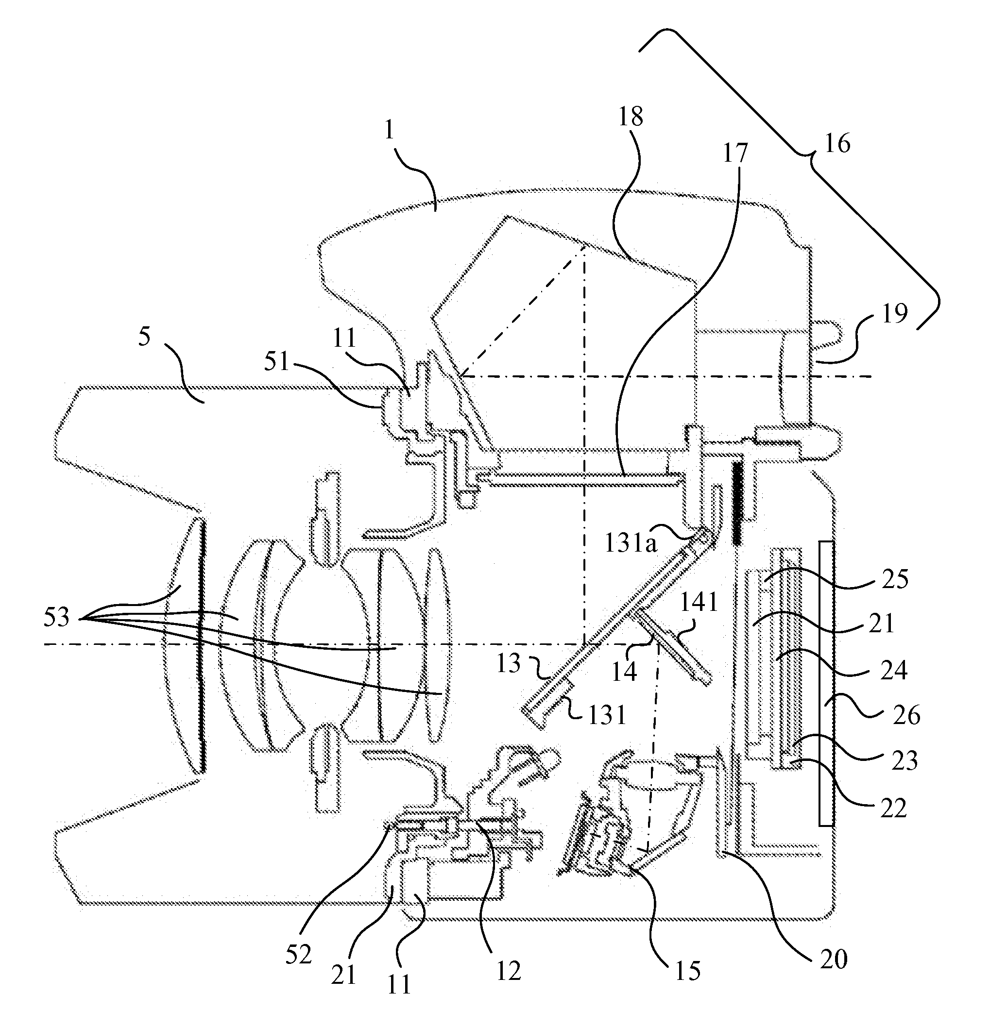
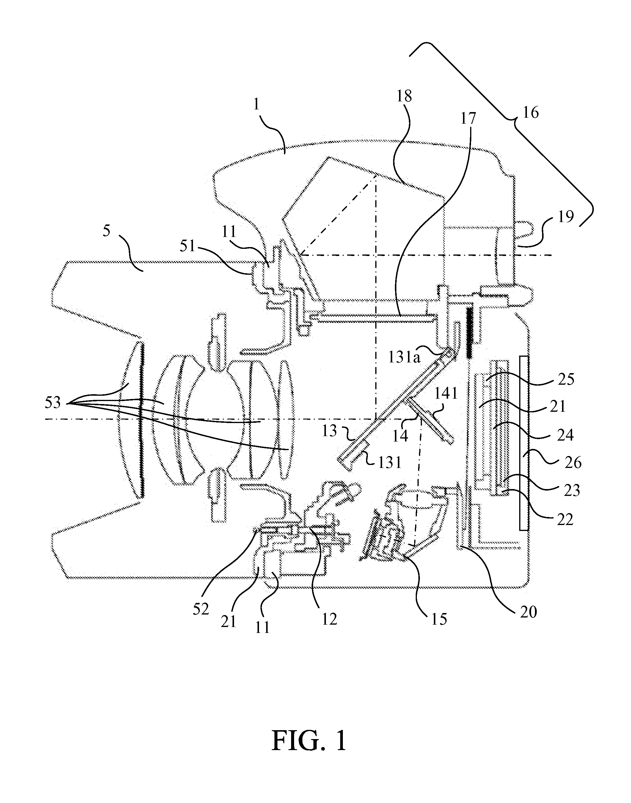
[0048]FIG. 1 a central sectional view of a digital single lens reflex camera body (hereinafter referred to as “camera”) 1 and an interchangeable lens 5 as an image pickup apparatus according to this embodiment of the present invention.

[0049]The interchangeable lens 5 is detachably fixed to the camera 1 by attachment of a mount portion 11 of the camera 1 side and a mount portion 51 of the interchangeable lens 5 side. When the interchangeable lens 5 is attached to the camera 1, a contact portion 12 of the camera 12 electrically couples with a contact portion 52 of the interchangeable lens 5. Thereby, the camera 1 detects attachment of the interchangeable lens 5. Additionally, the camera 1 supplies power to the interchangeab...


PUM


Abstract

A shutter apparatus includes a blade member, a blade moving member, a locking member, a cam member, and a restriction member. The cam member moves the locking member from the locking position to the non-locking position so that the blade moving member moves from the closing position to the opening position. The restriction member moves from the non-restriction position to the restriction position after the blade moving member moves from the closing position to the opening position. The cam member moves the locking member in a direction opposite to a direction from the non-locking position to the locking position so that the locking member moves the restriction member from the restriction position to the non-restriction position.

Description

BACKGROUND OF THE INVENTION[0001]1. Field of the Invention[0002]The present invention relates to an image pickup apparatus such as a shutter apparatus and a digital camera including a shutter.[0003]2. Description of the Related Art[0004]Japanese Patent Laid-Open No. (“JP”) 2007-316503 proposes an image pickup apparatus and a shutter apparatus, which perform an image pickup operation with a combination of a focal plane shutter and an electronic shutter. This image pickup apparatus starts an exposure due to charge storage start scan and finishes an exposure operation due to a travelling of blade groups composed of mechanical shutters. In this shutter apparatus, when a charge lever performs a release of a fasten locking member after a driving lever is sucked and held due to an energization to an electric magnet, the blade groups moves from a state closing a shutter opening to a state opening the shutter opening (return operation). After that, when the charge lever performs a release of...

Claims


Application Information

Patent Timeline
Patent Type & Authority Applications(United States)
IPC IPC(8): G03B9/36G03B19/12
CPCG03B19/12G03B9/36G03B9/42G03B2217/002H04N23/55G03B9/08
Inventor SAKAI, MASANORIITO, KOICHI
Owner CANON KK
Learn More