
Auto-Cleaning Marination Filter for Poultry Injector System

a technology of marination filter and injector system, which is applied in the direction of filtration separation, sedimentation settling tank, separation process, etc., can solve the problems of reducing the pressure in the discharge line downstream of the filter, clogging all the screens with solid particles, and reducing the flow rate of the filter. , to achieve the effect of eliminating extra time and resources and easy flow through the filter

Active Publication Date: 2014-09-18
JOHN BEAN TECH CORP
View PDF5 Cites 10 Cited by
  • Summary
  • Abstract
  • Description
  • Claims
  • Application Information

AI Technical Summary

Benefits of technology

The invention is an auto-cleaning filter that has a wiper inside a cylindrical filtering screen to remove solids that accumulate on the internal screen surface and through the screen perforations. The wiper continuously moves along the screen and removes the solids along the entire surface area, keeping the screen clean and unclogged with particles. This ensures that the brine can flow freely through the filter and to the injection head. The solids are flushed out by the brine flowing through the filtering screen in an opposite direction of normal flow, which moves them through a gap in the wiper. The particles are then moved out of the filter to a rotating cylindrical screen over the brine tank that includes an auger to pass the solids to a waste bin. This eliminates the need for extra time and resources to switch and clean filters throughout the shift. In summary, the invention allows for continuous and easy filtration without the need for constant maintenance and cleaning.

Problems solved by technology

One drawback of the prior art system is that, throughout the process, all of the screens become clogged with solid particles that have been separated from the brine when filtered and the filters lose surface area.
This causes a decrease in pressure in the discharge line downstream of the filter and prohibits the injector from injecting product consistently during the full run time shift.
Another drawback is that as the standard filters become clogged, an operator has to manually switch from the filter in use to a secondary filter so the previous one can be removed and cleaned prior to being used again.
During a normal shift, this can happen many times which requires substantial time and resources to keep the system running correctly.

Method used


Image

  • Auto-Cleaning Marination Filter for Poultry Injector System
  • Auto-Cleaning Marination Filter for Poultry Injector System
  • Auto-Cleaning Marination Filter for Poultry Injector System

Examples


Embodiment Construction

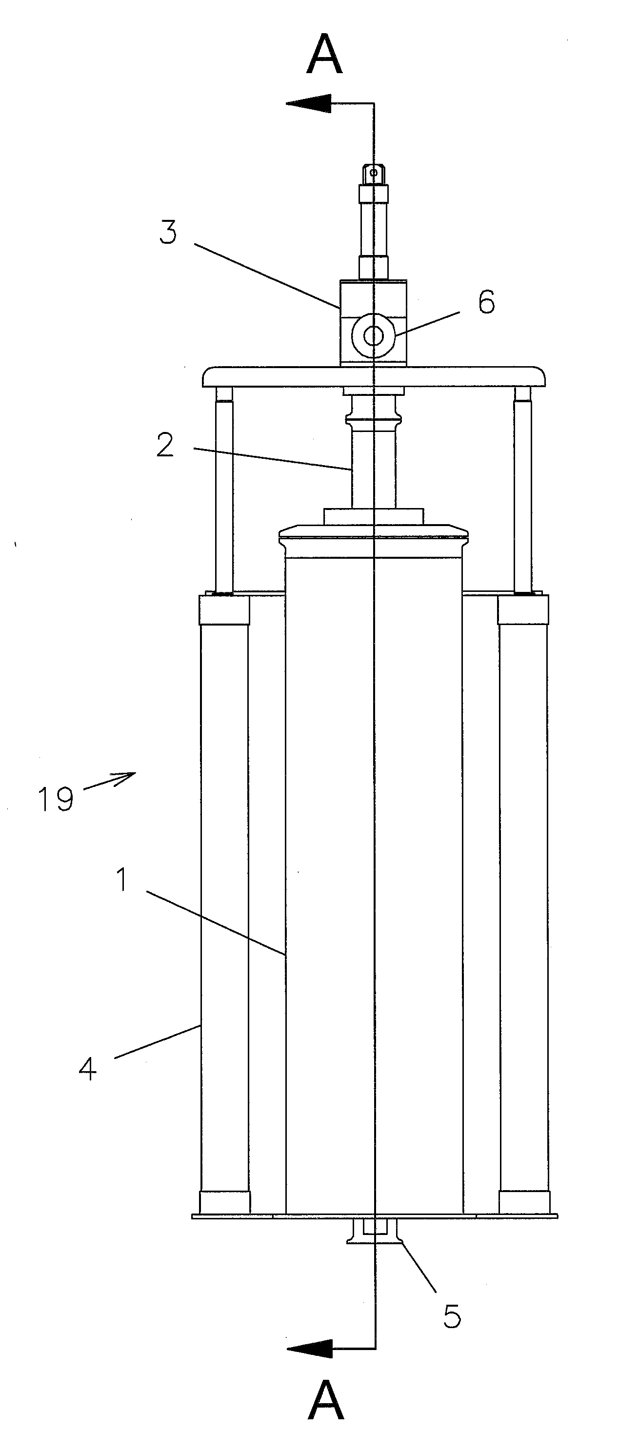
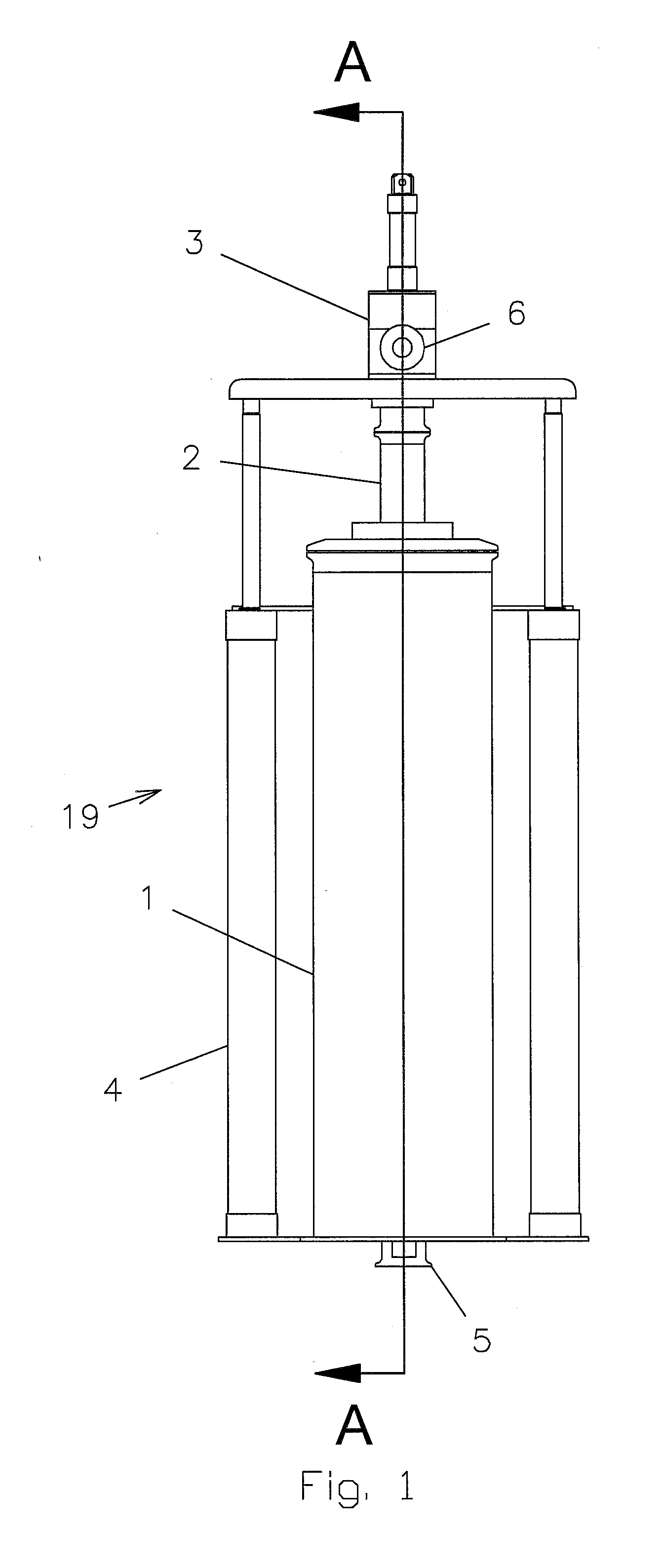
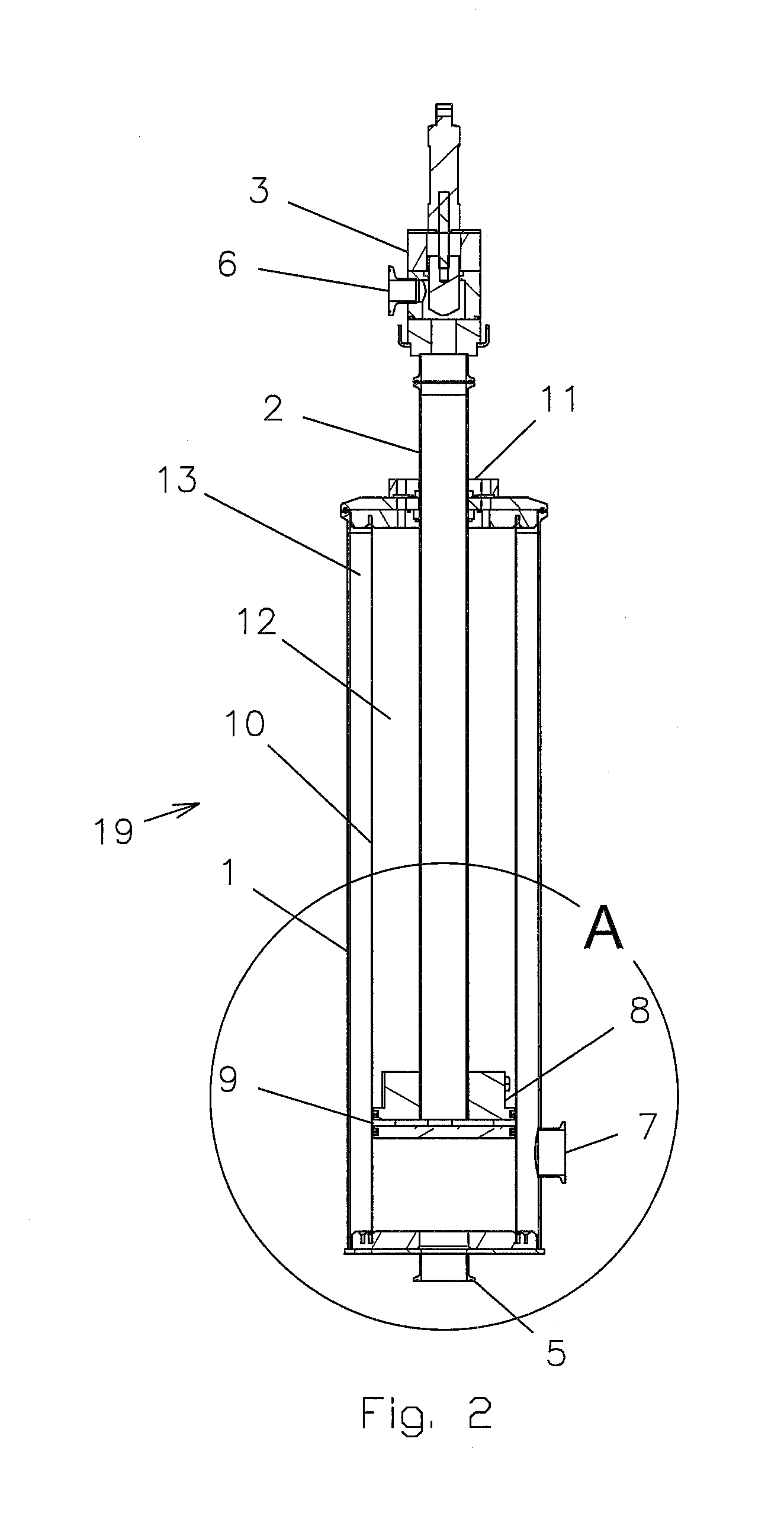
[0013]With reference to FIGS. 1-4, the preferred embodiments of the present invention may be described. The auto-cleaning filter 19 of the present invention includes an outer filter housing 1 and a filter screen 10. The outer filter housing 1 and filter screen 10 are preferably cylindrical. The cylindrical filter screen 10 allows the liquid brine to pass through its perforations, but collects any solids against its surface. FIG. 2 shows a sectional view illustrating the internal components of the auto-cleaning filter 19. On the inside surface of the cylindrical screen 10 is a wiper 8 that is attached to a tube 2. The wiper 8 is continuously moved or stroked to the top of the tube 2 and the screen 10 and then to the bottom of the tube 2 and the screen 10 by pneumatic cylinders 4. This cycle is repeated continuously so the wiper 8 is constantly moving inside the cylindrical surface of the screen 10.

[0014]The filter 19 has a brine inlet 5 on the bottom of the housing 1 and a brine outl...


PUM

PropertyMeasurementUnit
Pressureaaaaaaaaaa
Volumeaaaaaaaaaa

Abstract

An auto-cleaning marination filter for a poultry injector system including an outer housing having a liquid inlet and outlet, a screen that allows passage of liquids and impedes passage of solid particles, and a wiper surrounded by said screen for removing solid particles attached to the screen by reverse flow of the liquid through a gap in the wiper.

Description

CROSS-REFERENCE TO RELATED APPLICATIONS[0001]This application claims the benefit of U.S. Provisional Application No. 61 / 798,607, entitled “Auto-Cleaning Marination Filter for Injector” and filed on Mar. 15, 2013. The complete disclosure of said provisional patent application is hereby incorporated by reference.STATEMENT REGARDING FEDERALLY SPONSORED RESEARCH OR DEVELOPMENT[0002]Not applicableBACKGROUND OF THE INVENTION[0003]1. Field of the Invention[0004]The present invention relates to automated poultry needle injector systems that mechanically pump a brine solution into poultry products using a pump pulling from a brine tank and a bank of needles mounted in an injection head.[0005]2. Brief Description of the Related Art[0006]Prior art needle injection systems pull a brine solution from a tank by means of a centrifugal pump, and the discharge goes through a series of filters and screens to separate the solid particles from the brine solution before it goes into the injection head. ...

Claims


Application Information

Patent Timeline
IPC IPC(8): B01D29/64A23L1/318B01D29/23A23L13/75
CPCB01D29/6484A23L1/3182B01D29/23B01D29/117A23L13/50A23L13/75
Inventor ESTES, ANDREW C.ESTES, JEREMY B.
Owner JOHN BEAN TECH CORP
Learn More