

Pinch Decompression in Radial Crimp Press Machines
a crimping machine and crimping machine technology, applied in metal-working machines, metal working equipment, manufacturing tools, etc., can solve the problems of reducing affecting the quality of crimping,
- Summary
- Abstract
- Description
- Claims
- Application Information
AI Technical Summary
Benefits of technology
Problems solved by technology
Method used
Image

Examples
Embodiment Construction
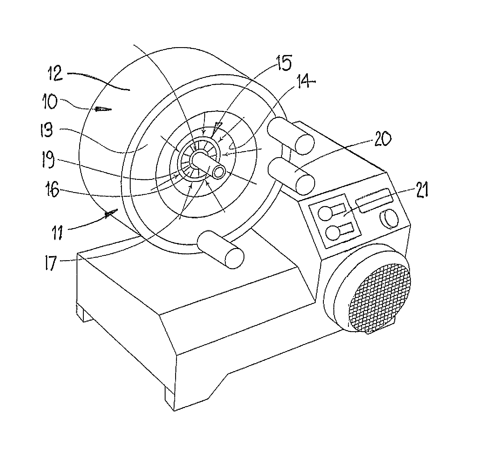
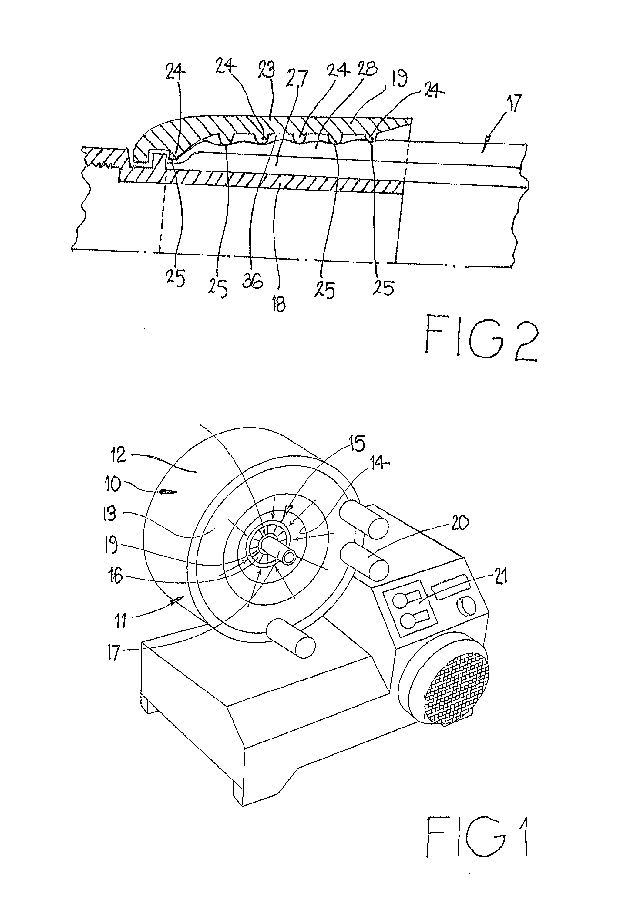
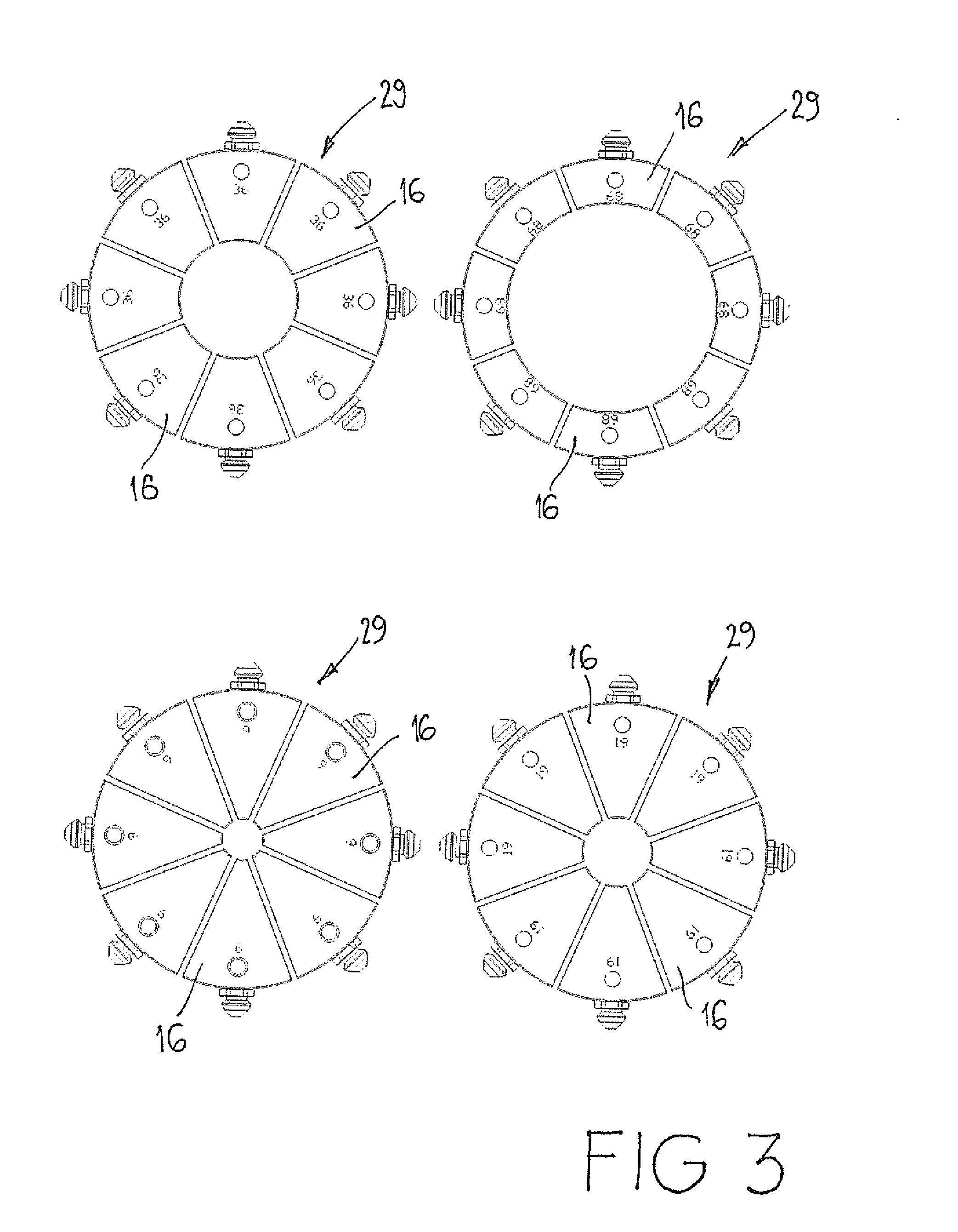
[0023]FIG. 1 shows schematically a crimp press 10 including a housing 11 with a front wall 13 and circumferential wall 12, the front wall 13 having a central opening 14 providing access to a work area 15. Within the work area 15 are a plurality of die elements 16 that are mounted to move in a radial direction inwardly and outwardly. An annular piston member (not shown) is axially movable within the housing 11 and has ramp surfaces engageable with ramp surfaces on circumferentially outer faces of the die elements 16 to effect inward radial movement of the die elements 16 as the piston member moves towards the front wall 13. Movement of the piston member is achieved by pressurized hydraulic fluid being introduced into a chamber to drive the piston member forward towards the front wall 13. In operation, a hose 17 with an end fitting 18 and ferrule 19 loosely connected is positioned within the work area 15 with the die elements 16 in a radially withdrawn position. The die elements 16 ar...
PUM
| Property | Measurement | Unit |
|---|---|---|
| Force | aaaaa | aaaaa |
Abstract
Description
Claims
Application Information