Traumatic bone fracture repair systems and methods

Active Publication Date: 2014-09-25
4-WEB
View PDF6 Cites 89 Cited by
  • Summary
  • Abstract
  • Description
  • Claims
  • Application Information

AI Technical Summary

Benefits of technology

[0008]Various embodiments of implant systems and related apparatus, and methods of operating the same are described herein. In various embodiments, an implant for interfacing with a bone structure includes a web structure, including a space truss, configured to interface with human bone tissue. The space truss includes two or more planar truss units having a plurality of struts joined at nodes.
[0009]In an embodiment, an implant for interfacing with a bone structure, includes: a web structure that includes a space truss composed of two or more planar truss units having a plurality of struts joined at nodes, wherein the web structure is configured to interface with human bone tissue; and one or more channels formed in the web structure, the one or more channels extending through the web structure and having an channel exit in at least two sides of the web structure. One or more fasteners are positionable within the channels, wherein the fasteners couple the web struct

Problems solved by technology

For example, large rims may impede bone growth and reduce the size of the bone column fusing the superior and inferior vertebral bodies.
This may increase the pressure on smaller areas of the vertebral endplates and may potentially lead to stress risers in the vertebral endplates.
Further, while bone graft material is often used in conjunction with implants

Method used


Image

  • Traumatic bone fracture repair systems and methods
  • Traumatic bone fracture repair systems and methods
  • Traumatic bone fracture repair systems and methods

Examples


Embodiment Construction

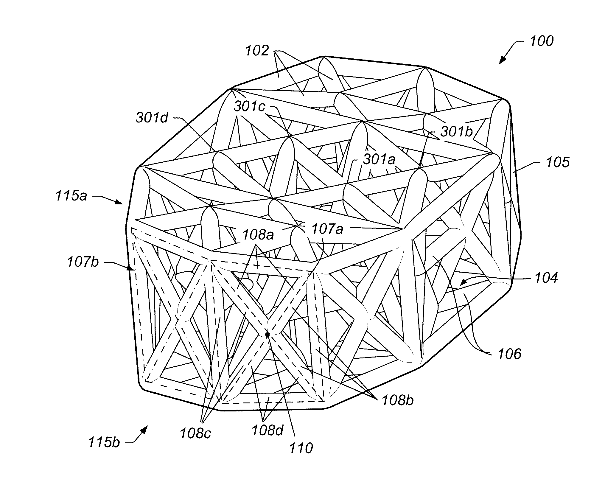
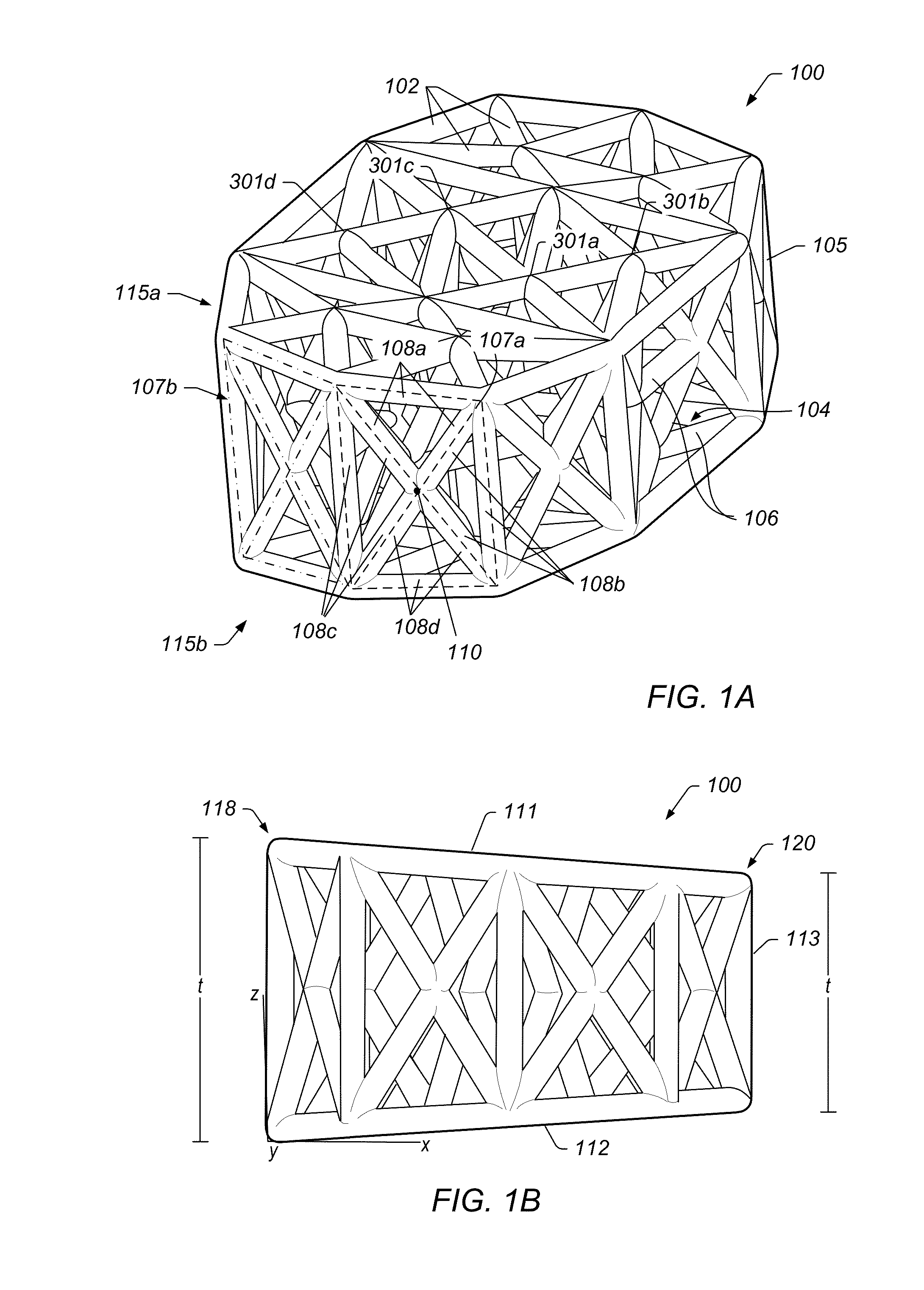
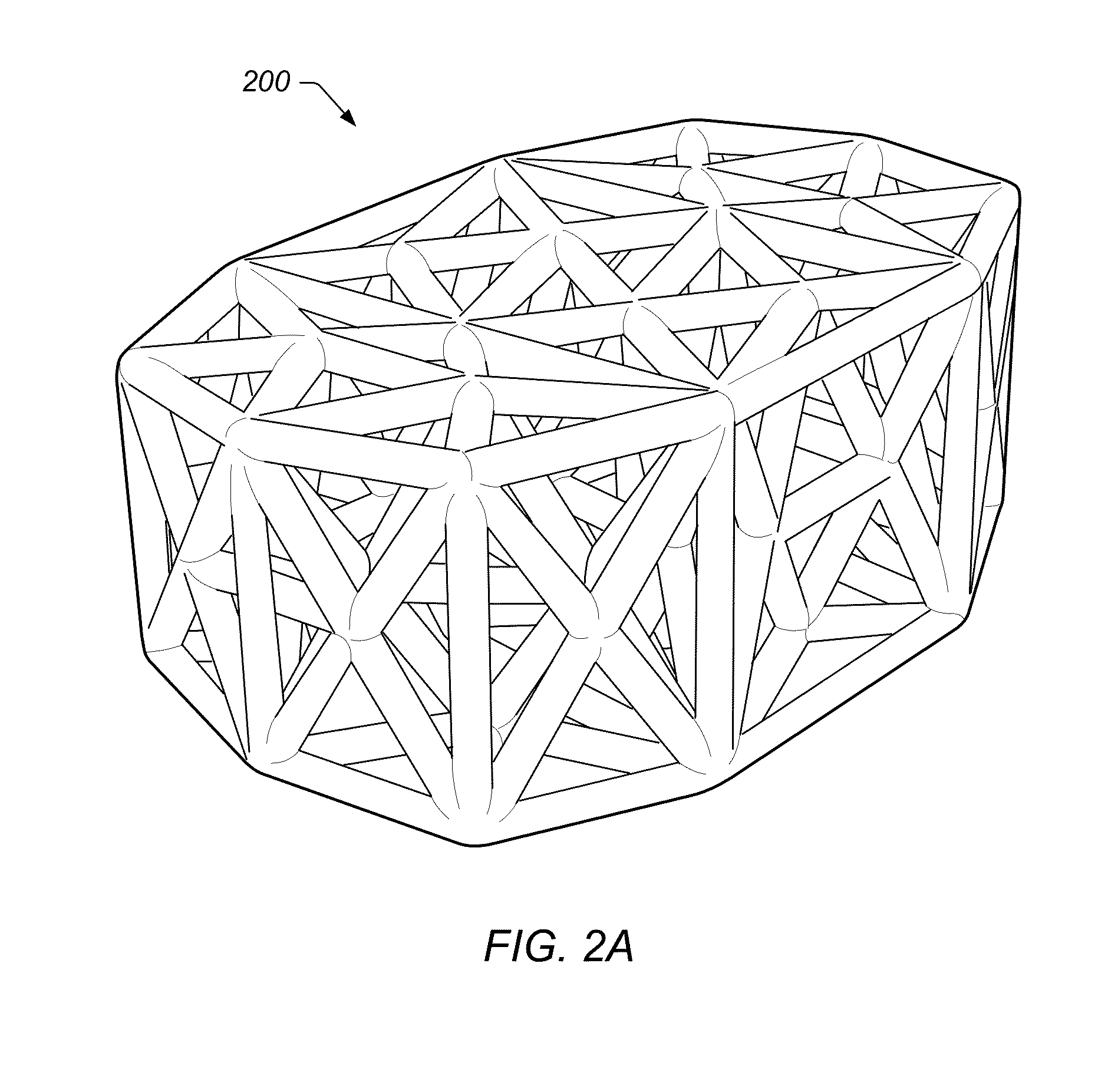
[0038]FIGS. 1A-1B illustrate views of implant 100, according to an embodiment. The specifically depicted implant 100 may be used, for example, in anterior lumbar inter-body fusion (ALIF) or posterior lumbar inter-body fusion (PLIF), however, it should be understood that implant 100 nay have a variety of shapes suitable for bone fusion applications. In some embodiments, implant 100 may include a web structure with one or more trusses 102 (e.g., planar and space trusses). Implant 100 may be used in various types of implants for humans or animals such as spinal implants, corpectomy devices, knee replacements, hip replacements, long bone reconstruction scaffolding, and cranio-maxifacial implants. Other implant uses are also contemplated.

[0039]As used herein a “truss structure” is a structure having one or more elongate struts connected at joints referred to as nodes. Trusses may include variants of a pratt truss, king post truss, queen post truss, town's lattice truss, planar truss, spa...


PUM

PropertyMeasurementUnit
Angleaaaaaaaaaa
Structureaaaaaaaaaa

Abstract

A hand and/or wrist implant, including a web structure having a space truss with two or more planar truss units having a plurality of struts joined at nodes. The web structure is configured for the repair of traumatic bone fractures.

Description

PRIORITY CLAIM[0001]This application claims priority to U.S. Provisional Application Ser. No. 61 / 801,524 entitled “TRAUMATIC BONE FRACTURE REPAIR SYSTEMS AND METHODS” filed Mar. 15, 2013, which is incorporated herein by reference in its entirety.BACKGROUND[0002]1. Field of the Invention[0003]The present invention relates generally to medical devices and, more specifically, to implants.[0004]2. Description of the Related Art[0005]Implants may be used in human and / or animals to support and / or secure one or more bones. For example, implants may be used in the spine to support and / or replace damaged tissue between the vertebrae in the spine. Once implanted between two vertebrae, the implant may provide support between the two vertebrae and bone growth may take place around and through the implant to at least partially fuse the two vertebrae for long-term support. Implants may include relatively large rims with solid material that may cover, for example, 50% of the area that interacts wi...

Claims


Application Information

Patent Timeline
IPC IPC(8): A61F2/28
CPCA61F2/28A61F2/2803A61F2/447A61F2/4611A61F2002/2835A61F2002/30153A61F2002/30156A61F2002/30158A61F2002/30179A61F2002/30273A61F2002/30275A61F2002/30281A61F2002/30599A61F2002/30841A61F2002/30914A61F2002/3092A61F2002/30943A61F2002/30952A61F2002/30953A61F2002/30957A61F2002/30962A61F2002/30968A61F2002/3097A61F2310/00017A61F2310/00023A61F2310/00029A61F2310/00047A61F2310/00179A61F2310/00598A61F2310/00796A61F2310/00958A61F2310/0097A61F2310/00976A61F2/30907A61F2002/30593A61F2002/3028
Inventor HUNT, JESSEE
Owner 4-WEB
Why Eureka
Try Eureka