
Enhanced co-formed/meltspun fibrous web structure

a co-formed, fiber-based technology, applied in the direction of filament/thread forming, synthetic resin layered products, packaging, etc., can solve the problems of opacity, texture and feel of web material, tensile strength, drape, surface friction, etc., to achieve the effect of enhancing the tensile strength, reducing the opacity of the web material, and improving the elasticity

Inactive Publication Date: 2018-01-04
THE PROCTER & GAMBLE COMPANY
View PDF5 Cites 49 Cited by
  • Summary
  • Abstract
  • Description
  • Claims
  • Application Information

AI Technical Summary

Benefits of technology

The patent text describes a fibrous web structure that can be used as a wet wipe substrate. The structure is made through a co-forming process where polymer resin is melt spun and directed onto a moving forming belt with cellulose fibers. The resulting structure is strong enough to maintain its shape when wetted with a lotion, but also soft enough to give a comfortable sensory experience to the user. The structure has suitable absorbency, porosity, and surface texture to effectively absorb and carry the lotion, as well as clean soiled skin. The patent also discusses the addition of scrim layers to reduce lint release during use. The technical effects of the patent include improving the performance of wipes by making them better cleaning with less material, and identifying the best proportions of components in the scrim layers to make the structure more desirable for use as a wet wipe substrate.

Problems solved by technology

However, the ways in which inclusion of scrim layers, and the relative proportions of components of the scrim layers and intermediate or core layers, affect properties such as tensile strength, drape, surface friction, opacity, texture and feel of the web material, have not been apparent or predictable.

Method used


Image

  • Enhanced co-formed/meltspun fibrous web structure
  • Enhanced co-formed/meltspun fibrous web structure
  • Enhanced co-formed/meltspun fibrous web structure

Examples


Embodiment Construction

Definitions

[0034]As used herein, the articles “a” and “an” when used herein, for example, “an anionic surfactant” or “a fiber” is understood to mean one or more of the material that is claimed or described.

[0035]“Basis Weight” is the weight per unit surface area (in a machine-direction / cross-direction plane) of a sample of web material (on one side), expressed in grams / meter2 (gsm). Basis weight may be specified in manufacturing specifications, and also may be measured, and reflects the weight of the material prior to addition of any liquid composition.

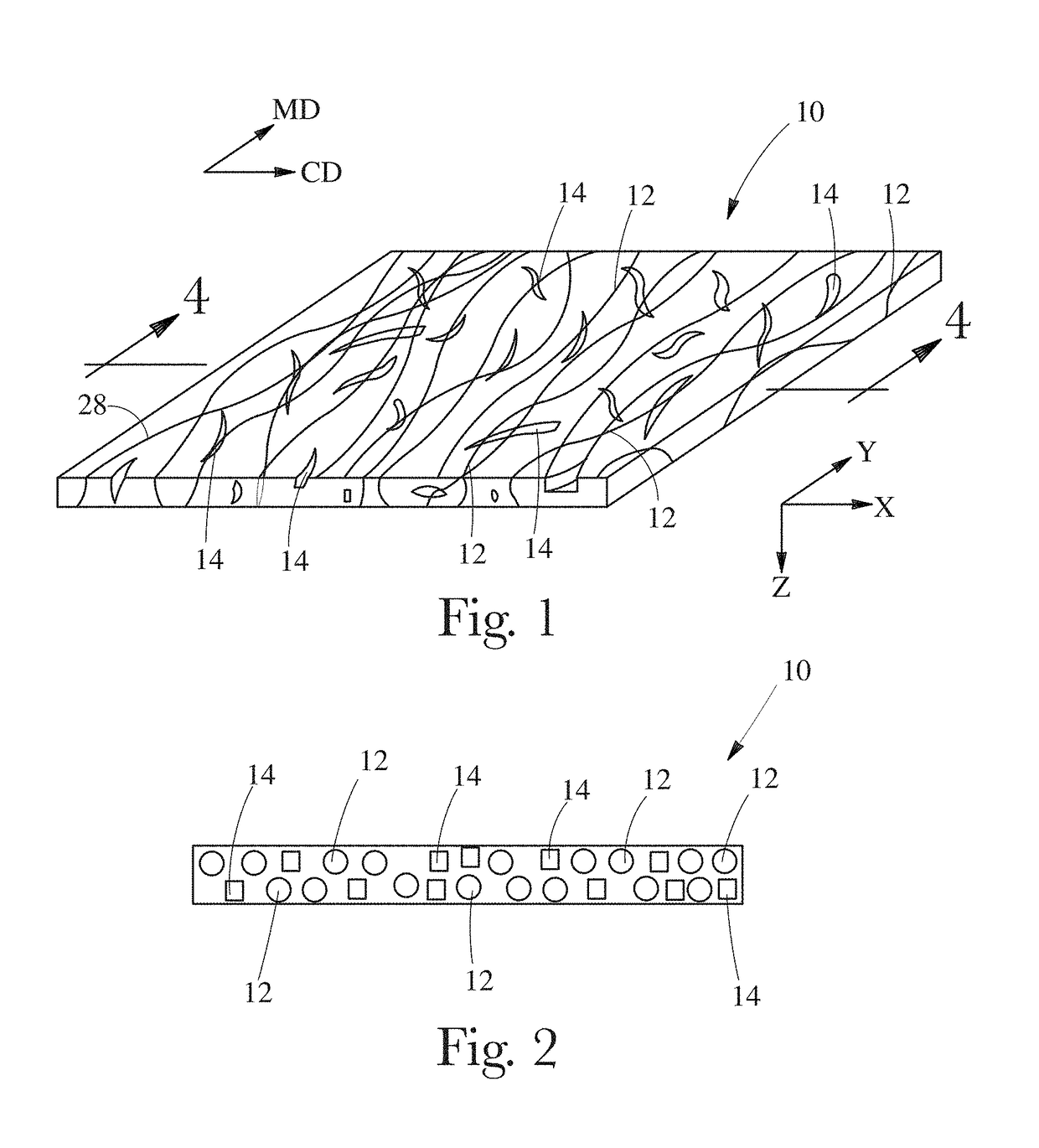
[0036]“Co-formed fibrous web structure” as used herein means that the fibrous web structure comprises an intermixed and / or entangled blend of at least two different materials wherein at least one of the materials comprises filaments, such as spun polymer filament (e.g., filaments spun from polypropylene resin), and at least one other material, different from the first material, comprises fibers. In one example, a co-formed fibrous web...


PUM

PropertyMeasurementUnit
Size distributionaaaaaaaaaa
Fractionaaaaaaaaaa

Abstract

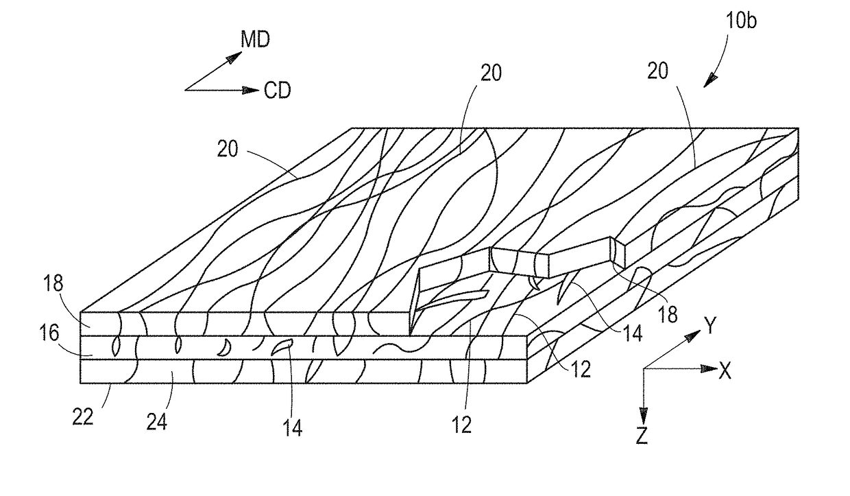
An enhanced, co-formed fibrous web structure is disclosed. The web structure may have a co-formed core layer sandwiched between two scrim layers. The core layer may be formed of a blend of cellulose pulp fibers and melt spun filaments. The scrim layers may be formed of melt spun filaments, and the filaments forming one or both scrim layers may have a number average diameter of 4.5 μm or less. Filaments of one or both of the scrim layers, and optionally the core layer, may also be meltblown filaments. Alternatively, the filaments forming the scrim layers may constitute from 1 to 13 percent of the weight of the structure. Alternatively, the scrim layers may have a combined basis weight of from 0.1 gsm to less than 3.0 gsm. A method for forming the structure, including direct formation of layers, is also disclosed.

Description

BACKGROUND OF THE INVENTION[0001]Wet wipes cut from fibrous web structures formed in a co-forming process have been marketed for several years. The co-forming process involves melt spinning continuous filaments from polymer resin, and simultaneously, directing an air stream with entrained distributed cellulose fibers together with the filaments, typically into a co-forming box or similar blending apparatus, blending the filaments and fibers, and directing the blend along to a collecting / forming structure such as a moving forming belt. The filaments may be spun and introduced into the airstream carrying the cellulose fibers, or an airstream carrying the cellulose fibers may be introduced into the pathway of the filaments following spinning, the effect being the deposit of an entangled blend of filaments and fibers onto the moving forming structure and accumulation and formation of a batt thereof. Upon subsequent consolidation and bonding of the batt, a cohesive fibrous web structure ...

Claims


Application Information

Patent Timeline
IPC IPC(8): D04H3/007D01D5/098A45D44/00D04H3/016D04H3/153D04H3/04D04H3/015
CPCD04H3/007D04H3/015D01D5/0985D04H3/016D04H3/153A45D2200/1027A45D44/00D10B2201/01D10B2321/022D10B2509/00D04H3/04B32B5/022B32B7/04B32B7/12B32B5/26B32B27/12B32B25/10B32B25/08B32B2260/023B32B2260/048B32B2262/0253B32B2262/062B32B2262/067B32B2262/0276B32B2262/0238B32B2262/14B32B2262/0261B32B2307/718B32B2307/728B32B2307/73B32B2307/546B32B2307/538B32B2307/54B32B2307/41B32B2307/554B32B2307/5825B32B2555/02B32B2555/00B32B2307/732B32B5/08D04H1/425D04H1/559D04H1/4374D04H1/56D04H1/43835D04H1/43838B08B1/143
Inventor BURT, ADAM JAMESALGERS, JOHN DANIELCAMERON, CHRISTOPHER SCOTT
Owner THE PROCTER & GAMBLE COMPANY
Learn More