Seating structure having flexible seating surface

a seating structure and flexible technology, applied in the field of chairs and seating, can solve the problems of excessive heat build-up between the seating surface and the occupant, difficult if not impossible to properly vary the firmness, and relatively inefficient process, and achieve the effects of superior surface adjustment, greater rigidity, and greater comfor

Inactive Publication Date: 2005-01-06
HERMAN MILLER INC
View PDF94 Cites 44 Cited by
  • Summary
  • Abstract
  • Description
  • Claims
  • Application Information

AI Technical Summary

Benefits of technology

[0008] The present invention relates to an improved method of constructing seating surfaces, which provides greater comfort through superior surface adjustment for a variety of users. The seating surface construction is comprised of a plurality of support sections, or bosses / platforms and of a plurality of web connectors interconnecting the support sections. The support sections, or bosses / platforms are more rigid than their corresponding web connectors. A variety of methods are disclosed for making the bosses / platforms exhibit a greater degree of rigidity than the web connectors. One such method disclosed is to alter the thickness of the bosses / platforms versus the web connectors. And another method is to provide the bosses / platforms with stiffening geometry that provides a greater degree of rigidity than the web connectors. Such stiffening means could be the addition of one or more returns or ribs. Another is to make the bosses / platforms out of a different material than the web connectors. And another is to construct the webs with a geometry that acts as a hinge. Yet another is to make the given geometry out of a material that can exhibit stretch in addition to flexure. The invention also provides greater airflow to contact areas of the occupant's body, because foam is not necessary to create a comfortable seating surface. Additionally, the seating surface is more efficient and economical to produce.
[0009] So, an object of the present invention is to provide a new and improved method of chair seat and back pan construction, which provides greater comfort for the user. A further object of the invention is to provide a new and improved method of chair seat back pan construction, which provides superior surface adjustment for a variety of users. A further object of the invention is to provide a new and improved method of chair seat back pan construction, which provides greater airflow to contact areas of the occupant's body. A further object of the invention is to provide a new and improved method of chair seat back pan construction, which is more efficient and economical to produce.

Problems solved by technology

Several problems exist with each of these approaches.
In the case of simply using foam padding, under normal manufacturing conditions it is difficult if not impossible to properly vary the amount of firmness and thus support from one area of a cushion to another.
Additionally, having to use foam can lead to excessive heat-build-up between the seating surface and the occupant.
One of the problems with foam is the forming / molding of it.
Current manufacturing technology makes it a relatively inefficient process compared with the manufacture of the other components that make up a chair of seating surface.
Another problem inherent to the use of foam is that in order to achieve a finished look the cushions must be upholstered.
When a manufacturer is forced to upholster a cushion a number of problem issues arise.
Additionally, the amount of change can vary from fabric to fabric which results in an unpredictability of the firmness of a cushion from one manufactured unit to the next.
Such sizing can be difficult as a result of the differing mechanical properties found from one fabric to another.
Variations in the amount of stretch can lead to other problems.
This approach also suffers from the aforementioned problems associated with using variable fabrics.
This leads to an additional molding etc. that often also has to be upholstered.
The other reality of cushion upholstery, regardless of the techniques used, is that whether it is done in a small shop or in a production situation, it is consistently the most labor-intensive aspect of chair / seating construction.
In the case of incorporating flex into the shells of a chair, no geometry to date has achieved the proper amount of flex in the right areas to give correct ergonomic comfort for a wide range of individuals.
In the case of a sling approach, the curves imparted on the sling by the frame are simple in nature (non-compound) and thus cannot provide the proper contouring necessary for ergonomic comfort.
Also, this approach leads to “hammocking”.
Hammocking is when the sling is pressed in one area; the areas immediately adjacent have the tendency of folding inward, squeezing the occupant, again not yielding the proper ergonomic curvatures.
An additional problem with sling chairs is that if the manufacturer makes the supporting sling surface taut enough to properly support a large-heavy person, the tension on the sling will be too great for a smaller person, resulting in discomfort.
Unfortunately, this leads to the manufacturer having to tool three independent products instead of one, and the manufacturers, wholesalers, and retailers having to stock (in this example) three times the quantity of product.
Additionally, the end user is stuck with a chair that at some point in the future may be the wrong size.

Method used


Image

  • Seating structure having flexible seating surface
  • Seating structure having flexible seating surface
  • Seating structure having flexible seating surface

Examples


Embodiment Construction

[0044] While the invention will be described in connection with a preferred embodiment, it will be understood that I do not intend to limit the invention to that embodiment. On the contrary, I intend to cover all alternatives, modifications and equivalents within the spirit and scope of the invention.

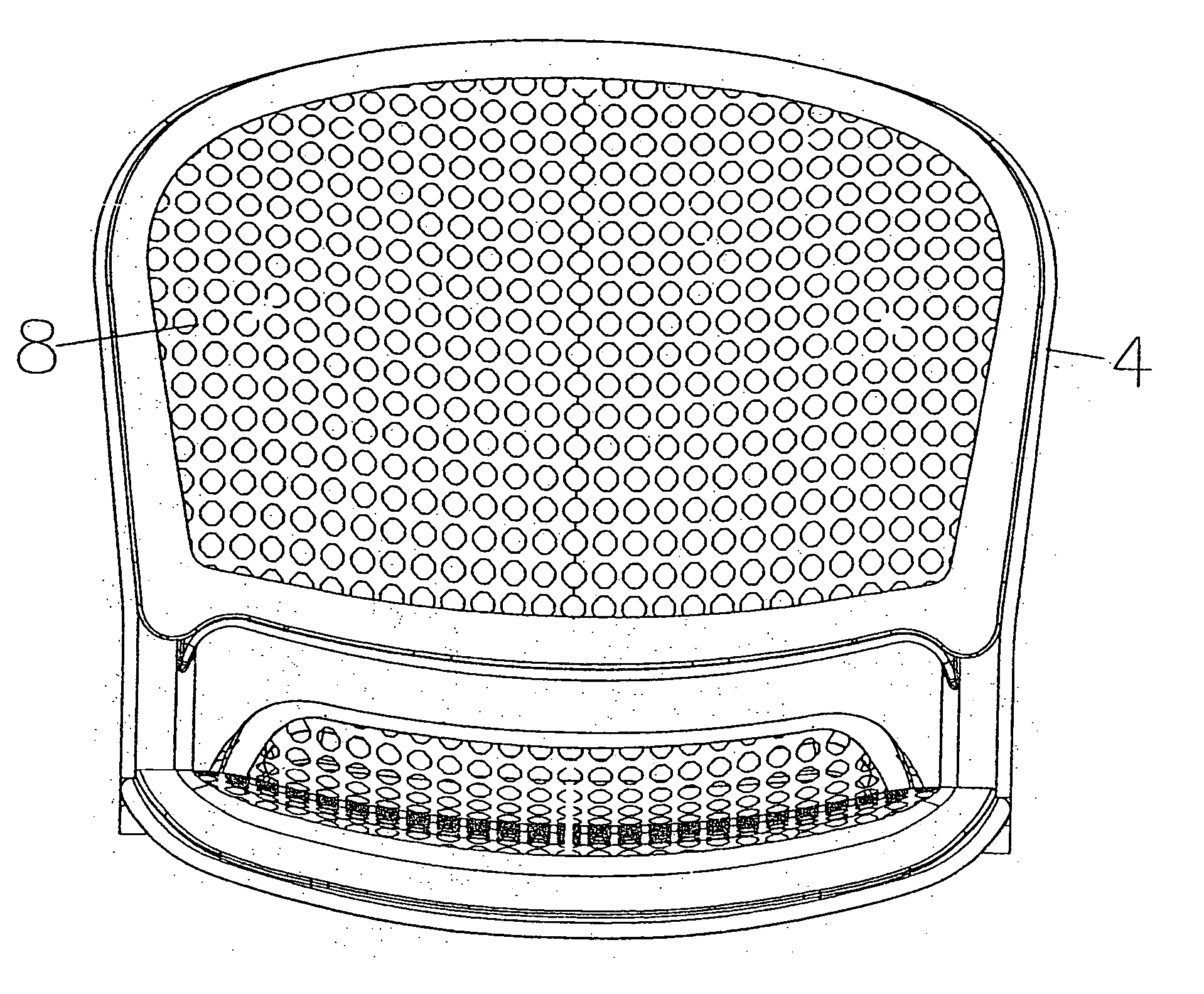
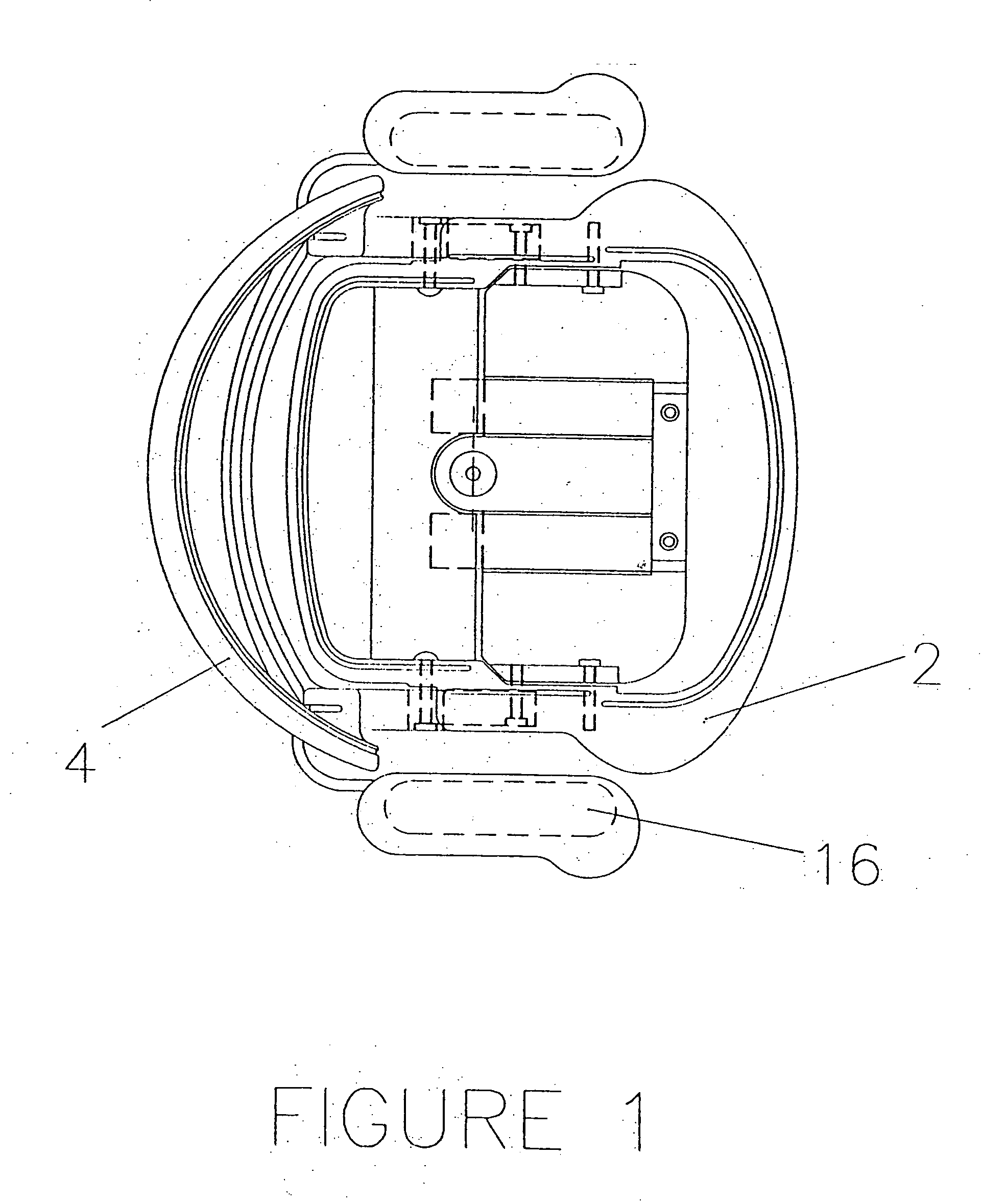
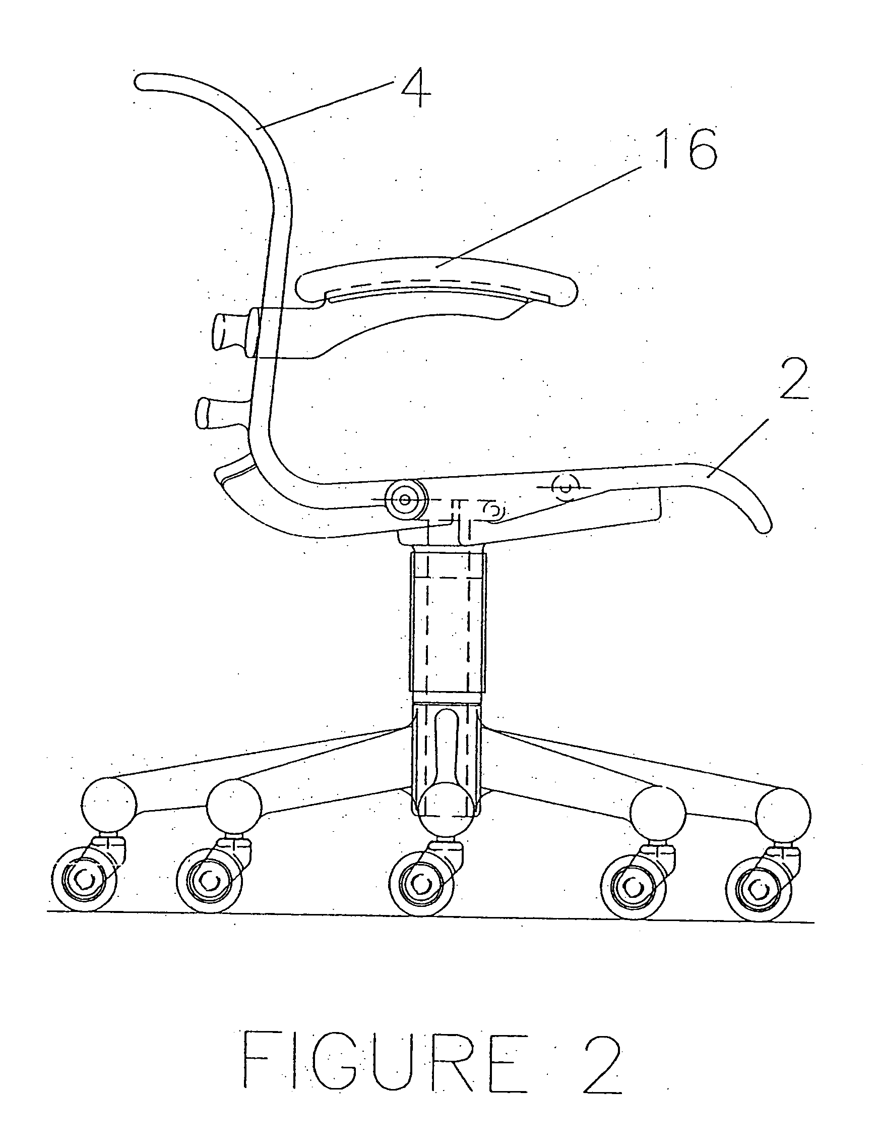
[0045] Referring to FIG. 10 a top view of the seat-pan seating surface and its support frame can be seen. And by referring to FIGS. 3-6, the shells or pans can be seen separate from the frames, and the frames can be seen separate from the seating surface shells or pans in FIGS. 1,2,7,8, and 9. Also, it should be noted that a separate peripheral support frame is not a necessity of the invention, for the shells could be self-supporting with an integral structure. Additionally for clarification, a seat-pan, or back-pan seating surface refers to a structure which may be the primary surface, as in a plastic or wood chair, or a structure which may accept foam and upholstery and thus not be t...


PUM

PropertyMeasurementUnit
seating structureaaaaaaaaaa
web structuresaaaaaaaaaa
movementaaaaaaaaaa

Abstract

A seating structure includes a plurality of boss structures arranged in a pattern and a plurality of web structures joining adjacent boss structures within the pattern. At least some of the web structures are non-planar and at least some adjacent web structures are spaced apart such that they define openings therebetween. In another aspect, the seating structure includes a plurality of boss structures arranged in a pattern and defining a support surface and a plurality of web structures joining adjacent boss structures within the pattern. At least some adjacent web structures are spaced apart and shaped such that they define substantially non-circular openings therebetween when viewed in a direction substantially perpendicular to the support surface.

Description

[0001] This application is a continuation of U.S. patent application Ser. No. 09 / 897,153, filed Jun. 29, 2001, which claims the benefit of U.S. Provisional Application No. 60 / 215,257, filed July 3, 2000, the entire disclosures of which are hereby incorporated herein by reference.FIELD OF INVENTION [0002] The present invention relates to chairs and seating normally associated with but not limited to residential or commercial office work. These chairs employ a number of methods of to enhance the user's comfort and promote ergonomically healthy sitting. These methods include various forms of padding and flexing of the seat and back as well as separate mechanical controls that control the overall movement of the seat and back. BACKGROUND OF THE INVENTION [0003] Various approaches to making a chair's seat and back form fitting for various users are known in the industries of seating manufacture. These approaches range from the rather traditional use of contouring synthetic foam, to seat / ...

Claims


Application Information

Patent Timeline
Patent Type & Authority Applications(United States)
IPC IPC(8): A47C5/12A47C7/02A47C7/16A47C7/28
CPCA47C1/03A47C1/03277A47C3/12A47C5/12A47C7/46A47C7/16A47C7/28A47C7/285A47C7/02
Inventor CARUSO, JEROME CARMELCARUSO, STEVEN JEROME
Owner HERMAN MILLER INC
Why Eureka
Try Eureka