Support Frame Assembly And Method Of Forming A Support Frame Assembly

a technology of support frame and assembly method, which is applied in the direction of girders, heat collector mounting/supports, lighting and heating apparatus, etc., can solve the problems of labor-intensive assembly of components, large load on the support structure, and unnecessarily becoming physically larger, so as to reduce assembly time and cost, facilitate the adaptation, and reduce the effect of strict tolerances

Inactive Publication Date: 2014-05-01
MAGNA INTERNATIONAL INC
View PDF6 Cites 44 Cited by
  • Summary
  • Abstract
  • Description
  • Claims
  • Application Information

AI Technical Summary

Benefits of technology

[0009]According to at least one aspect of the present invention, a support frame assembly for supporting a solar device is provided. The support frame assembly includes at least one support arm assembly with at least two rails at least partially spaced from one another and converging towards one another from a first end to a second end. At least two web structures are spaced from one another and extend between the first and second rails with each web structure extending between and being attached to the at least two rails to interconnect the rails. At least one of the web structures has a base attached to one of the rails and at least two legs extending to the other of the rails and an opening between the legs. The web structures can be easily adapted to support arm assemblies having various shapes, sizes and designs. The web structures also allow for less strict tolerances between the components of the support frame assembly and for reduced assembly time and cost as compared to other known support frame assemblies.
[0010]According to another aspect of the invention, at least one of the web structures is shaped and sized to at least partially nest within the opening of another of the web structures. The nesting relationship of the web structures allows the components of the support frame assembly to be more efficiently shaped and shipped to an assembly location. Additionally, the nesting relationship allows multiple web structures to be stamped at one time from a single blank with very little material waste.
[0011]According to yet another aspect of the invention, the web structures are formed of a different, lighter material than the rails. Thus, the mass of the support arm assemblies may be reduced without compromising their structural integrity.

Problems solved by technology

As solar energy devices are now being required to satisfy ever-larger energy requirements, they necessarily become physically larger.
The weight of the support structure itself, and that of the attached solar devices along with wind loads and / or snow loads, can cause significant loads on the support structure.
As such, tracking systems are found in virtually all concentrator applications because such systems do not produce energy unless oriented closely toward the sun.
Such techniques require pre-assembly and transportation of large frame sections, often to locations that are difficult to access, or they require labor intensive assembly of components on-site, often under unfavorable conditions.

Method used


Image

  • Support Frame Assembly And Method Of Forming A Support Frame Assembly
  • Support Frame Assembly And Method Of Forming A Support Frame Assembly
  • Support Frame Assembly And Method Of Forming A Support Frame Assembly

Examples


Embodiment Construction

[0025]The following description is presented to enable a person skilled in the art to make and use the invention, and is provided in the context of a particular application and its requirements. Various modifications to the disclosed embodiments will be readily apparent to those skilled in the art, and the general principles defined herein may be applied to other embodiments and applications without departing from the scope of the invention. Thus, the present invention is not intended to be limited to the embodiments disclosed, but is to be accorded the widest scope consistent with the principles and features disclosed herein.

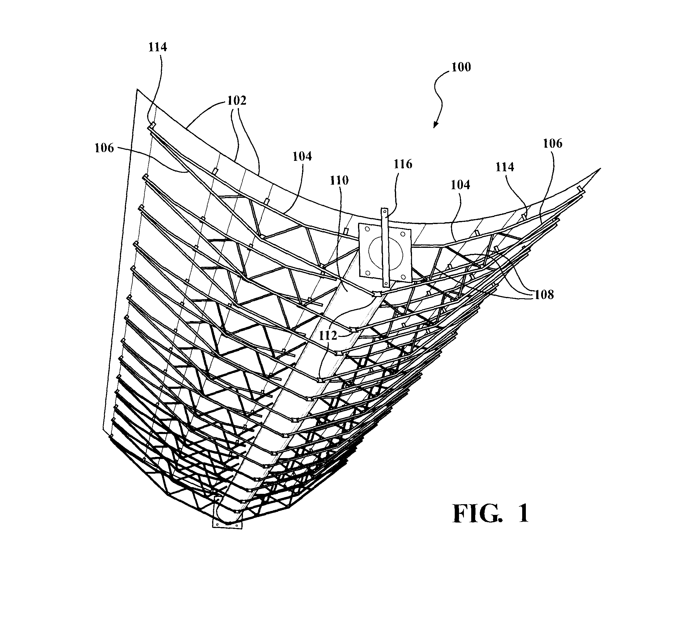
[0026]In order to facilitate a better understanding of the features that are present in at least some of the embodiments of the present invention, one known type of support frame assembly 100 is described herein below, with reference to FIG. 1. The known support frame assembly 100 includes a parabolic, generally trough-shaped array of mirror elements 102 for re...


PUM

PropertyMeasurementUnit
web structuresaaaaaaaaaa
web structureaaaaaaaaaa
torqueaaaaaaaaaa

Abstract

At least one aspect of the present invention is related to a support frame assembly for supporting a solar device, such as an array of mirror elements and / or photovoltaic panels. The support frame assembly includes a plurality of support arm assemblies, each of which includes a pair of rails and a plurality of web structures interconnecting the rails. Specifically, each of the web structures has a base which is attached to one of the rails and a pair of legs extending towards and attached to the other of the rails. The web structures are preferably formed through a single stamping process with at least one of the web structures being at least partially in a nesting relationship with another of the web structures.

Description

CROSS-REFERENCE TO PRIOR APPLICATION[0001]This PCT patent application claims the benefit of U.S. Provisional Patent Application Ser. No. 61 / 489,518 filed May 24, 2011, entitled “Support System And Method For Supporting Solar Related Devices,” the entire disclosure of the application being considered part of the disclosure of this application and hereby incorporated by reference.FIELD OF THE INVENTION[0002]The present invention relates generally to support frame assemblies for solar related devices, and more particularly to a support frame assembly for supporting a solar device and method of forming a support frame assembly to support a solar device.BACKGROUND OF THE INVENTION[0003]As solar energy devices are now being required to satisfy ever-larger energy requirements, they necessarily become physically larger. In some devices, the aggregate surface of the solar device being supported by the support structure may typically approach hundreds of square meters. Consequently, a reliabl...

Claims


Application Information

Patent Timeline
Patent Type & Authority Applications(United States)
IPC IPC(8): F24J2/52E04C3/08
CPCF24J2/14F24J2/16F24J2/5233Y02E10/47F24J2/5203E04C2003/0491F24J2/5254Y02E10/45E04C3/08E04C3/09F24S23/74F24S23/77F24S25/13F24S25/632F24S2025/013Y10T29/49627F24S25/30Y02E10/40
Inventor WERNER, MARK F.SCHWARTZ, STEVEN JOSEPHLALKA, II, MICHAEL STEPHEN
Owner MAGNA INTERNATIONAL INC
Why Eureka
Try Eureka