Grill smoker apparatus

a grille and smoker technology, applied in the direction of vehicle components, transportation and packaging, climate change adaptation, etc., can solve the problems of large, cumbersome hardware associated with a stand-alone smoker, and many consumers do not have the additional space for an additional enclosure, so as to improve the air flow

Active Publication Date: 2014-10-09
VINETT KEVIN
View PDF67 Cites 20 Cited by
  • Summary
  • Abstract
  • Description
  • Claims
  • Application Information

AI Technical Summary

Benefits of technology

[0007]The smoked flavor imparted to the food is dependent upon the nature and amount of smoke to which the food is exposed, as well as the duration of exposure to the smoke during cooking. The more smoke produced by the smoking device, the faster the smoke flavor is imparted to the food. Consequently, more smoke flavor can be imparted to the food in less cooking time when the smoking device produces more smoke under any given cooking conditions. With more smoke, a piece of food that is cooked more rapidly at a higher temperature can be infused with as much smoke flavor as a similar piece of food cooked for a longer period of time at a lower cooking temperature. Also, with more smoke, a piece of food that is cooked to a lesser degree of doneness (e.g., rare) can have the same degree of smoky flavor imparted to it as a similar piece of food cooked at the same temperature for a longer period of time to a greater degree of doneness (e.g., well done).
[0009]Many existing smoking devices that can be used with conventional barbecue grills are placed on top of the open grill, which serves solely as the heat source for the device but does not permit the use of the grill's cooking surface because the device is otherwise a closed system in which the meat is placed within the device along with the source of the smoke. The cooking capacity of those types of devices is, therefore, limited to something less than that of the grill. Because much of the heat generated by the grill is dissipated to the outside of the smoking device, these types of grill-top smokers consume more energy to produce the heat necessary to cook the meat and to cause the smoke producing material to smoke, and their lesser energy efficiency makes them more expensive to operate.
[0021]Another object of the present disclosure is to provide an air gap between the carrier and the container to provide improved air flow to the smoke producing material retained in the carrier.

Problems solved by technology

One problem associated with conventional food-smoking devices is the large, cumbersome hardware associated with a stand-alone smoker.
Such consumers often do not want to purchase an additional enclosure for smoking food.
Additionally, many consumers do not have the additional space for an additional enclosure such as stand-alone smoker on their patios or decks.
However, this conventional method of producing smoke has many drawbacks.
It is often difficult to produce a desired amount of smoke, or to control smoke production, using this crude method.
These devices also have problems and generally do not produce a desirable amount of smoke for smoking food.
Many existing smoking devices that can be used with conventional barbecue grills are placed on top of the open grill, which serves solely as the heat source for the device but does not permit the use of the grill's cooking surface because the device is otherwise a closed system in which the meat is placed within the device along with the source of the smoke.
The cooking capacity of those types of devices is, therefore, limited to something less than that of the grill.
Because much of the heat generated by the grill is dissipated to the outside of the smoking device, these types of grill-top smokers consume more energy to produce the heat necessary to cook the meat and to cause the smoke producing material to smoke, and their lesser energy efficiency makes them more expensive to operate.
Other smoking devices that are designed to be used with a conventional barbecue grill under a closed cover may allow the end-user to use the grill's cooking surface, but do not optimize the amount of smoke produced by the smoke producing material either because the source of heat used to heat the smoke producing material is diffuse and less efficient at heating the smoke producing material or because the arrangement of the smoke producing material does not optimize the production of smoke by the heated smoke producing material.
Still other existing smoking devices used with conventional grills are limited with respect to the smoke producing material that may be used.
In many existing devices, the heat is directed to the smoke producing material from only a single direction and / or the air flow about the heated smoke producing material is limited thus limiting the smoke producing materials' exposure to the heat, heating the smoke producing material unevenly or incompletely, and / or limiting the amount of smoke produced by the smoke producing material.
This type of installation is burdensome on users of conventional grills.
Additionally, many conventional grill users do not like the idea of drilling holes in their expensive grills.
Another problem associated with conventional external smoking devices is exposure to the weather.
By placing a smoker device on the exterior of a grill, rain, wind and snow can damage and cause corrosion in the smoker.
Additionally, insects and animals may form nests in such external smoker devices.
Another problem with conventional smoker devices that are rigidly affixed to a grill is that the smoker device becomes immoveable upon installation.
This is an inconvenience for the user in the event the user desires to use the smoker apparatus on a different grill or transport the smoker apparatus independently of the grill to which it is attached.

Method used


Image

  • Grill smoker apparatus
  • Grill smoker apparatus
  • Grill smoker apparatus

Examples


Embodiment Construction

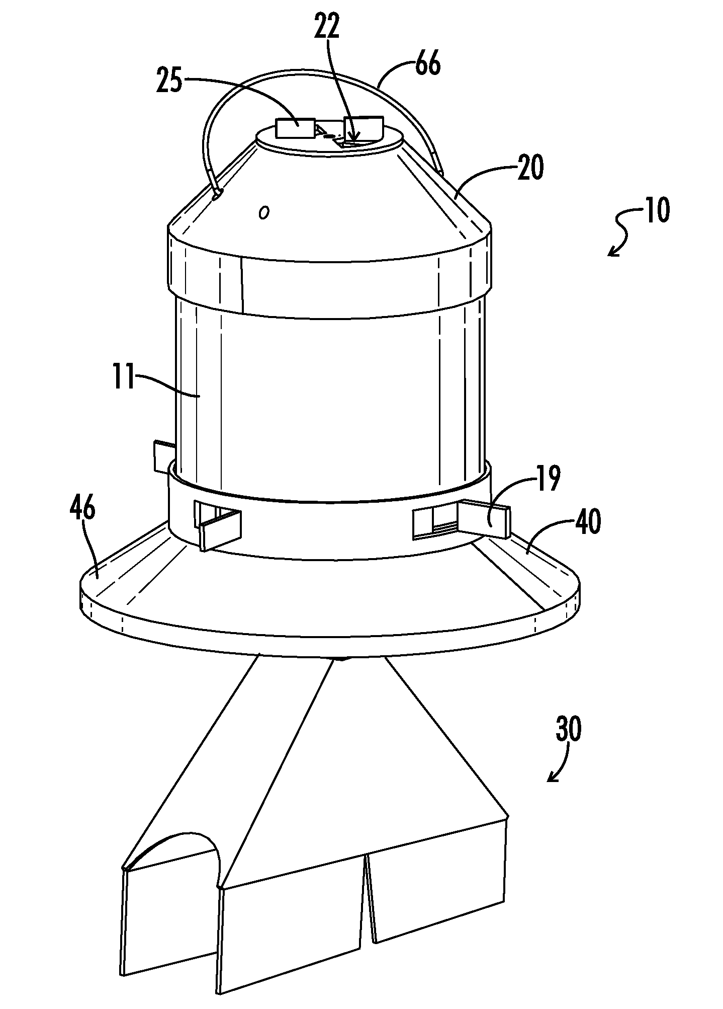
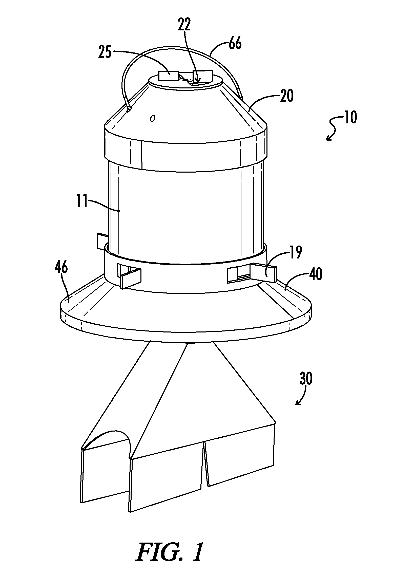
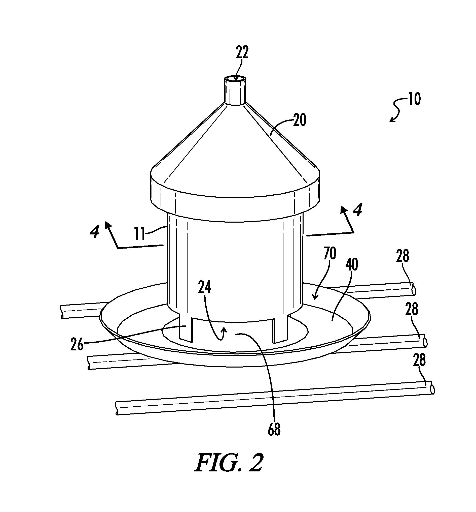
[0046]Throughout the specification and claims, the following terms take at least the meanings explicitly associated herein, unless the context dictates otherwise. The meanings identified below do not necessarily limit the terms, but merely provide illustrative examples for the terms. The meaning of “a,”“an,” and “the” may include plural references, and the meaning of “in” may include “in” and “on.” The phrase “is an embodiment” as used herein does not necessarily refer to the same embodiment, although it may. It is understood that in the drawings not all reference numbers are included in each drawing, for the sake of clarity. In addition, positional terms such as “upper,”“lower,”“side,”“top,”“bottom,”“inner,”“outer,”“vertical,”“horizontal,” etc. refer to the apparatus when in the orientation shown in the drawing. The skilled artisan will recognize that objects in accordance with the present disclosure can assume different orientations when in use.

[0047]Included herein are multiple i...


PUM


Abstract

A grill smoker apparatus provides a container and a cover. A carrier is disposed in the container. The carrier is configured to store smoke producing material such as wood chips. The carrier may be removable from the container for filling the container, for emptying the container, for replacing the container or for cleaning the smoker apparatus. The carrier includes an outer dimension smaller than the inner dimension of the container. As such, a carrier gap is defined between the inner container wall and the outer region of the carrier. The carrier gap may form a uniform, annular gap in some embodiments. Alternatively, the carrier gap has a non-uniform radial dimension around the perimeter of the container. The carrier gap provides enhanced airflow to the smoke producing material in the carrier for improving smoker performance. A heat concentrator also focuses heat to the smoker apparatus for igniting the smoke producing material.

Description

[0001]This nonprovisional utility patent application is a nonprovisional of and claims benefit and priority to U.S. provisional patent application number 61 / 787,800 entitled Smoker Apparatus filed Mar. 15, 2014, all of which is hereby incorporated by reference in its entirety.[0002]The present disclosure relates generally to an apparatus for smoking food and more particularly to an apparatus that provides a smoking apparatus for positioning inside a cooking enclosure such as a grill or smoker for smoking food.[0003]Devices for smoking food are generally known in the art. Some food smoking devices include self-contained enclosures in which the food to be smoked is placed. The enclosures can be closed and sealed to contain smoke that imparts flavor to the food, usually with a lid. Inside the enclosure, there is a support structure, such as a grid or platform, on which the meat or other food is placed. Smoke producing material such as charcoal or wood is also placed in the enclosure an...

Claims


Application Information

Patent Timeline
Patent Type & Authority Applications(United States)
IPC IPC(8): A23B4/052
CPCA23B4/052Y02A40/90
Inventor VINETT, KEVIN
Owner VINETT KEVIN
Why Eureka
Try Eureka